4-5
Cisco Secure Router 520 Series Software Configuration Guide
OL-14210-01
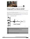
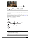
Chapter 4 Configuring PPP over ATM with NAT
Configure the ATM WAN Interface
Configure the ATM WAN Interface
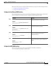
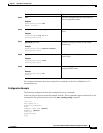
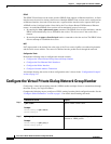
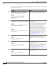
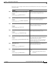
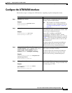
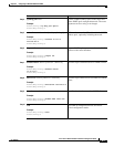
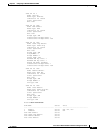
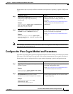
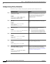
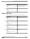
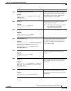
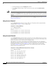
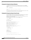
Perform these steps to configure the ATM interface, beginning in global configuration mode:
Command Purpose
Step 1
interface type number
Example:
Router(config)# interface atm 0
Router(config-if)#
Enters interface configuration mode for the ATM
interface (labeled ADSLoPOTS).
Note This interface was initially configured
during basic router configuration. See the
“Configure WAN Interfaces” section on
page 1-4.
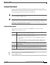
Step 2
pvc vpi/vci
Example:
Router(config-if)# pvc 8/35
Router(config-if-atm-vc)#
Creates an ATM PVC for each end node (up to ten)
with which the router communicates. Enters ATM
virtual circuit configuration mode.
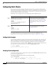
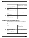
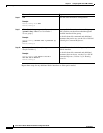
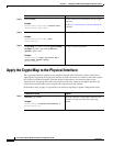
When a PVC is defined, AAL5SNAP
encapsulation is defined by default. Use the
encapsulation command to change this, as shown
in
Step 3. The VPI and VCI arguments cannot be
simultaneously specified as zero; if one is 0, the
other cannot be 0.
For details about this command and additional
parameters that can be set, see the Cisco IOS
Wide-Area Networking Command Reference.
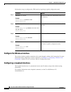
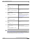
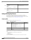
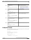
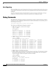
Step 3
encapsulation {aal5auto | aal5autoppp
virtual-template number [group group-name] |
aal5ciscoppp virtual-template number |
aal5mux protocol | aal5nlpid | aal5snap}
Example:
Router(config-if-atm-vc)# encapsulation
aal5mux ppp dialer
Router(config-if-atm-vc)#
Specifies the encapsulation type for the PVC and
points back to the dialer interface.
For details about this command and additional
parameters that can be set, see the Cisco IOS
Wide-Area Networking Command Reference.
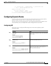
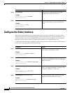
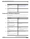
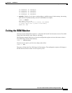
Step 4
dialer pool-member number
Example:
Router(config-if-atm-vc)# dialer
pool-member 1
Router(config-if-atm-vc)#
Specifies the ATM interface as a member of a
dialer profile dialing pool. The pool number must
be in the range of 1–255.