


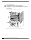

21
Catalyst 6000 Family Content Switching Module Installation and Configuration Note
78-11631-02 Rev. A0
Configuring the Content Switching Module
Configure the required parameters in the following sections:
• Configuring VLANs, page 21
• Configuring Server Farms, page 24
• Configuring Real Servers, page 25
• Configuring Policies, page 26
• Configuring Virtual Servers, page 30
After you configure the required load-balancing parameters on the CSM, you may configure the optional
parameters in the following sections:
• Configuring TCP Parameters, page 31
• Configuring Dynamic Feedback Protocol, page 31
• Configuring Redirect Virtual Servers, page 32
• Configuring Client NAT Pools, page 33
• Configuring Server NAT, page 34
To save or restore your configurations or to work with advanced configurations, refer to the following
sections:
• Writing and Restoring Configurations, page 34
• Configuration Examples, page 35
• Configuring Probes for Health Monitoring, page 46
• Configuring Route Health Injection, page 51
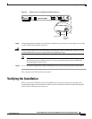
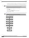
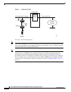
Configuring VLANs
The CSM requires configuration for client-side and server-side VLANs when you install the module in
a Catalyst 6500 series switch.
Note You must configure VLANs on the Catalyst 6000 family switch before you configure VLANs for the
CSM. VLAN IDs must be the same for the switch and the module.
The CSM dynamically allocates one client gateway to the active router for a total of two client gateways
for an HSRP group. You can configure a maximum of three HSRP groups on the client side of the CSM;
fewer if other routers exist on the client-side.
You need to create both a client- and server-side VLAN. (See Figure 8.)