


7
Catalyst 6000 Family Content Switching Module Installation and Configuration Note
78-11631-02 Rev. A0
Overview
Client-to-CSM-to-Server Traffic Flow
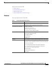
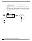
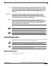
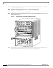
This section describes how the traffic flows between the client and server in a CSM environment.
(See Figure 3.)
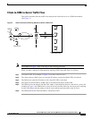
Figure 3 Client-to-Content Switching Module-to-Server Traffic Flow
Note The numbers in Figure 3 refer to the steps in the following procedure.
When you enter a request for information by entering a URL, the traffic flow is as follows:
Step 1 You enter a URL. (For example, in Figure 3 you enter www.fox.com.)
Step 2 The client contacts a DNS server to locate the IP address associated with the URL you entered.
Step 3 The DNS server sends the IP address of the virtual IP (VIP) to the client.
Step 4 The client uses that IP address (CSM VIP) to send the HTTP request to the CSM.
Step 5 The CSM receives the request with the URL, makes a load balancing decision, and selects a server. For
example, in Figure 3, the CSM selects a server (X server) from the www.fox.com server pool, replacing
its own VIP address with the address of the X server and forwards the traffic to the X server.
Step 6 The CSM performs the Network Address Translation (NAT).
.com
W
X
Y
Z
www.example.com
web server farm
5
2
3
4
6
7
47528
VIP
DNS server