


37
Catalyst 6000 Family Content Switching Module Installation and Configuration Note
78-11631-02 Rev. A0
Configuration Examples
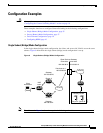
Secure (Router) Mode Configuration
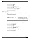
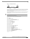
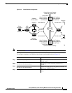
In secure (router) mode, the client- and server-side VLANs are on different subnets. Figure 10 shows
how the secure (router) mode configuration is set up.
Figure 10 Secure (Router) Mode Configuration
Note The addresses in Figure 10 refer to the steps in the following task table.
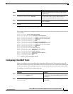
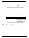
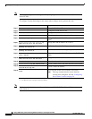
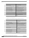
To configure Content Switching in secure (router) mode, perform this task:
Command Purpose
Step 1
Router(config)# vlan database
Enter the VLAN mode
1
.
Step 2
Router(vlan)# vlan 2
Configure a client-side VLAN
2
.
Step 3
Router(vlan)# vlan 3
Configure a server-side VLAN.
Step 4
Router(vlan)# exit
Exit to have the configuration take effect.
Step 5
Router(config)# ip slb vlan 2 client
Create the client-side VLAN 2 and enter the SLB
VLAN mode.
Step 6
Router(config-slb-vlan-client)# ip addr
192.158.38.10 255.255.255.0
Assign the CSM IP address on VLAN 2.
Step 7
Router(config-slb-vlan-client)# gateway
192.158.38.20
Define the client-side VLAN gateway to Router A.
Step 8
Router(config-slb-vlan-client)# gateway
192.158.38.21
Define the client-side VLAN gateway to Router B.