


42
Catalyst 6000 Family Content Switching Module Installation and Configuration Note
78-11631-02 Rev. A0
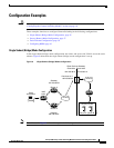
Configuration Examples
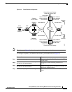
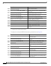
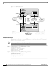
To configure the secondary (B) CSM for fault tolerance, perform this task (see Figure 12):
Step 5
Router(config-slb-vserver)# virtual
192.158.38.30 tcp www
Create a virtual IP address.
Step 6
Router(config)# ip slb vlan 3 server
Create the server-side VLAN 3 and enter the SLB
VLAN mode.
Step 7
Router(config-slb-vserver)# ip addr
192.158.39.10 255.255.255.0
Assign the CSM IP address on VLAN 2.
Step 8
Router(config-slb-vserver)# alias ip addr
192.158.39.20 255.255.255.0
Assign the default route for VLAN 2.
Step 9
Router(config) ip slb vlan 9 ft
Define VLAN 9 as a fault-tolerant VLAN.
Step 10
Router(config)# ip slb fault_tolerance
group ft-group-number vlan 9
Create the Content Switching primary and
secondary (A/B) group VLAN 9.
Step 11
Router(config)# vlan database
Enter the VLAN mode
1
.
Step 12
Router(vlan)# vlan 2
Configure a client-side VLAN2
2
.
Step 13
Router(vlan)# vlan 3
Configure a server-side VLAN3.
Step 14
Router(vlan)# vlan 9
Configure a fault-tolerant VLAN9.
Step 15
Router(vlan)# exit
Enter the exit command to have the configuration
take affect.
1. xEnter the exit command to leave a mode or submode. Enter the end command to return to the menu’s top level.
2. The no form of this command restores the defaults.
Command Purpose
Command Purpose
Step 1
Router(config)# ip slb vlan 2 client
Create the client-side VLAN 2 and enter the
SLB VLAN mode
1
.
1. Enter the exit command to leave a mode or submode. Enter the end command to return to the menu’s top level.
Step 2
Router(config-slb-vlan-client)# ip addr
192.158.38.40 255.255.255.0
Assign the Content Switching IP address on
VLAN 2.
Step 3
Router(config) ip slb vlan 9 ft
Define VLAN 9 as a fault-tolerant VLAN.
Step 4
Router(config-slb-vlan-client)# gateway
192.158.38.20
Define the client-side VLAN gateway.
Step 5
Router(config)# ip slb vserver vip1
Create a virtual server and enter the SLB vserver
mode.
Step 6
Router(config-slb-vserver)# virtual
192.158.38.30 tcp www
Create a virtual IP address.
Step 7
Router(config)# ip slb vlan 3 server
Create the server-side VLAN 3 and enter the
SLB VLAN mode.
Step 8
Router(config-slb-vserver)# ip addr
192.158.39.30 255.255.255.0
Assign the CSM IP address on VLAN 3.
Step 9
Router(config-slb-vserver)# alias
192.158.39.20 255.255.255.0
Assign the default route for VLAN 2.
Step 10
Router(config)# ip slb fault_tolerance group
ft-group-number ab vlan 9
Create the CSM primary and secondary (A/B)
group VLAN 9.