


3-11
Cisco 7200 VXR Installation and Configuration Guide
OL-5013-09
Chapter 3 Installing a Cisco 7200 VXR Router
Rack-Mounting a Cisco 7200 VXR Router
Installing the NPE-G1 and NPE-G2 Optical Cable-Management Bracket
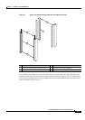
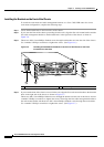
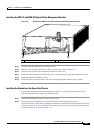
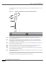
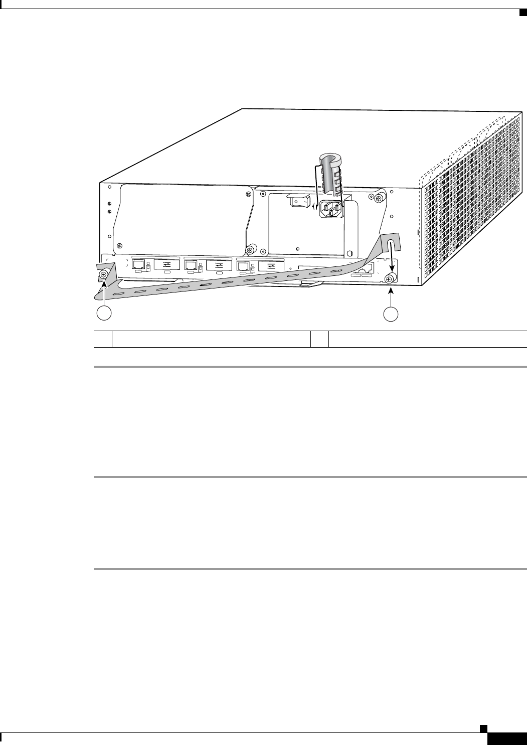
Figure 3-9 Installing the NPE-G1 and NPE-G2 Optical Cable-Management Bracket
Step 1 Loosen the left and right captive installation screws.
Step 2 Hold the cable-management bracket so that it is positioned as shown in Figure 3-9.
Step 3 Place the left end of the cable-management bracket over the screw.
Step 4 Rotate the cable-management bracket down, until it slides behind the right captive installation screw.
Step 5 Tighten both captive installation screws.
Step 6 Install the cables, and fasten them to the cable-management bracket with the straps provided.
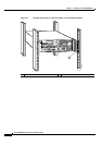
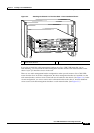
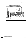
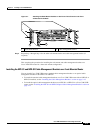
Installing the Brackets on the Rear of the Chassis
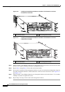
To install the rack-mount and cable-management brackets on a Cisco 7200 VXR router for a rear
rack-mount configuration, complete the following steps:
Step 1 Locate the threaded holes in the rear sides of the chassis.
Step 2 Align the first rack-mount bracket to the threaded holes in the right side of the chassis.
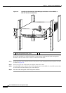
If you want the front of the chassis protruding from the rack, align the rack-mount bracket to the chassis
as shown in
Figure 3-10. If you want the front of the chassis recessed in the rack, align the rack-mount
bracket to the chassis as shown in Figure 3-11.
1 Left captive installation screw 2 Right captive installation screw
N
E
T
W
O
R
K
P
R
O
C
E
S
S
I
N
G
E
N
G
IN
E
-
3
0
0
GIGABIT ETH
ERN
ET 0/1
R
J
4
5
G
B
IC
E
N
R
X
T
X
L
I
N
K
C
O
N
S
OL
E
AU
X
GIGABIT E
THERNET 0/1
R
J
4
5
G
B
I
C
E
N
R
X
T
X
L
I
N
K
GIGABIT ETHERNET 0/1
R
J
4
5
G
B
I
C
E
N
R
X
T
X
L
I
N
K
C
P
U
R
E
S
E
T
C
O
M
P
A
C
T
F
L
A
S
H
P
O
W
E
R
O
K
S
L
O
T
A
C
T
I
V
E
NE
TW
OR
K PR
O
CESSING
E
NGIN
E - G
1
80680
2
1