


1-44
Cisco 7200 VXR Installation and Configuration Guide
OL-5013-09
Chapter 1 Cisco 7200 VXR Product Overview
Field-Replaceable Units
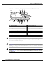
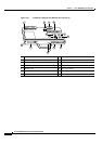
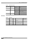
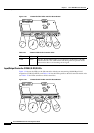
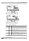
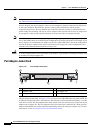
Figure 1-23 C7200-I/O-GE+E LEDs and CPU Reset Button
Input/Output Controller C7200-I/O-2FE/E LEDs
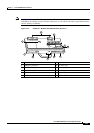
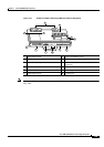
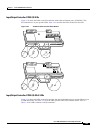
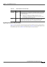
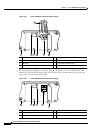
Figure 1-24 shows the LEDs on the I/O controller with the two autosensing 10/100-Mbps RJ-45
receptacles (C7200-I/O-2FE/E), and Table 1-28 lists the LEDs specific to this I/O controller model. Also
see Table 1-24 for LEDs common to all I/O controllers.
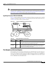
Figure 1-24 C7200-I/O-2FE/E LEDs and CPU Reset Button
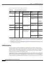
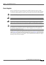
Tab le 1-27 C7200-I/O-GE+E I/O Controller LEDs
LED Color Function
LINK Green Indicates that the Ethernet RJ-45 receptacle has established a valid link
with the network. This LED remains off during normal operation of the
router unless there is an incoming carrier signal.
C
L
A
S
S
1
L
E
D
P
R
O
D
U
C
T
P
R
O
D
U
K
T
M
IT
K
L
A
S
S
E
1
L
E
D
P
R
O
D
U
I
T
A
V
E
C
V
O
Y
A
N
T
D
E
L
D
E
C
L
A
S
S
E
1
P
R
O
D
U
C
T
O
L
E
D
D
E
C
L
A
S
E
1
LINK
ETHERNET GIGABIT ETHERNET INPUT/OUTPUT CONTROLLER
CONSOLE
AUX
PORT
E 0
LINK
SLOT 0
PORT
GE 0
RX
TX
EJECT
PCMCIA
SLOT 1
ENABLED
C
P
U
R
E
S
E
T
IO
P
W
R
O
K
33446
CPU
RESET
IO PWR
OK
LINK
SLOT 0
SLOT 1
C7200-I/O-GE+E
ENABLED
LINK
GBIC
EN
DUAL FAST ETHERNET INPUT/OUTPUT CONTROLLER
CONSOLE
AUX
100 Mbps
LINK
100 Mbps
LINK
SLOT 0
EJECT
PCMCIA
SLOT 1
ENABLED
C
P
U
R
E
S
E
T
IO
P
W
R
O
K
33444
CPU
RESET
IO PWR
OK
100 Mbps
LINK
SLOT 0
SLOT 1
C7200-I/O-2FE/E
ENABLED
FE/E 0
FE/E 1