


3-44
Cisco 7200 VXR Installation and Configuration Guide
OL-5013-09
Chapter 3 Installing a Cisco 7200 VXR Router
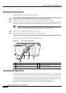
Connecting Power
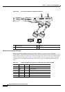
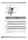
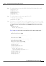
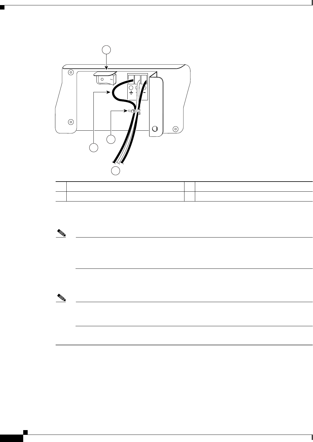
Figure 3-33 Connecting DC-Input Power
Step 6 Insert the stripped end of the +V lead all the way into the +V lead receptacle and tighten the receptacle
screw using the same 3/16-inch flat-blade screwdriver. Repeat this step for the –V lead.
Note Make sure the entire stripped end of each lead is inserted all the way into its receptacle. If any
exposed wire at the stripped end of a lead is visible after inserting the lead into its receptacle,
remove the lead from the receptacle, use the wire stripper to cut the stripped end of the lead, and
repeat Step 4 through Step 6.
Step 7 After tightening the receptacle screw for the ground, +V, and –V DC-input leads, use a cable tie (see
Figure 3-33) to secure the three leads to the power supply faceplate.
Note When securing the ground, +V, and –V DC-input leads to the power supply faceplate, leave a
small service loop in the ground lead to ensure that the ground lead is the last lead to disconnect
from the power supply if a great deal of strain is placed on all three leads (see Figure 3-33).
Step 8 Switch the circuit breaker to the on position.
This completes the procedure for connecting DC-input power. Your installation is complete. Proceed to
Chapter 4, “Observing System Startup and Performing a Basic Configuration” to start the router and to
perform a basic configuration.
1 Power switch 3 Cable tie
2 Ground lead service loop 4 DC power leads
84542
4
1
3
2