


3-29
Cisco 7200 VXR Installation and Configuration Guide
OL-5013-09
Chapter 3 Installing a Cisco 7200 VXR Router
Connecting I/O Controller, NPE-G1, or NPE-G2 Cables
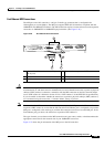
Note The mode-conditioning patch cord is required to comply with IEEE standards. The IEEE found that link
distances could not be met with certain types of fiber-optic cable cores. The solution is to launch light
from the laser at a precise offset from the center, which is accomplished by using the mode-conditioning
patch cord. At the output of the patch cord, the WS-G5486 or GBIC-LX/LH is compliant with the IEEE
802.3z standard for 1000BASELX.
A mode-conditioning patch cord can be used with the WS-G5486= or GBIC-LX/LH= to allow reliable
laser transmission between the single-mode laser source on the GBIC and a multimode fiber-optic cable.
Note We strongly recommend cleaning optical fiber connections before attaching cables to equipment. See the
“Fiber-Optic Cleaning Information” section on page 5-10 for information.
Gigabit Ethernet RJ-45 Connections on the NPE-G1 and NPE-G2
The NPE-G1 and NPE-G2 RJ-45 ports support 10BASET, 100BASETX, and 1000BASET and
1000BASEX protocols and the ports are compliant with IEEE 802.3, IEEE 802.3u, and IEEE 802.1q
standards.
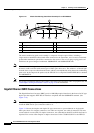
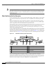
The RJ-45 ports support standard straight-through and crossover Category 5 UTP cables with RJ-45
connectors. (See
Figure 3-23 and Figure 3-24.) Cisco Systems does not supply Category 5 UTP cables;
these cables are available commercially.
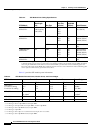
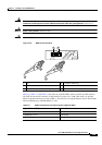
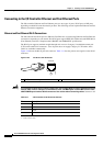
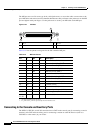
Figure 3-20 shows an RJ-45 port and connector. Table 3-10 lists the pinouts and signals for the RJ-45
port.
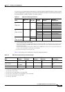
Note With reference to the RJ-45 pinouts in Table 3-10, proper common-mode line terminations should be
used for the unused Category 5 UTP cable pairs 4/5 and 7/8. Common-mode line termination reduces
electromagnetic interference (EMI).
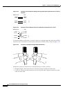
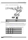
Depending on your RJ-45 interface cabling requirements, use the pinouts shown in Figure 3-23 and
Figure 3-24 for straight-through and crossover twisted-pair cable connections.
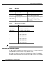
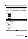
Tab le 3-10 NPE-G1 and NPE-G2 RJ-45 Port Pinouts
Pin 10/100 Signal Gigabit Ethernet Signal
1 Tx Data+
1
1. Tx Data = Transmit Data
Tx A+
2 Tx Data– Tx A–
3 Rx Data+
2
2. Rx Data = Receive Data
Rx B+
4 N/C Tx C+
5 N/C Tx C–
6 Rx Data– Rx B–
7 N/C Rx D+
8 N/C Rx D-