


2-3
Cisco 7200 VXR Installation and Configuration Guide
OL-5013-09
Chapter 2 Preparing for Installation
Site Requirement Guidelines
Site Requirement Guidelines
The environmental monitoring functionality in the Cisco 7200 VXR routers protects the system and
components from potential damage from overvoltage and overtemperature conditions. To ensure normal
operation and avoid unnecessary maintenance, plan your site configuration and prepare your site before
installation. After installation, make sure the site maintains an ambient temperature of 32•F through F through
104•F (0•C through 40•C), and keep the area around the chassis as free from dust as is practical. F (0•C through 40•C), and keep the area around the chassis as free from dust as is practical.
Planning a proper location for the Cisco 7200 VXR router and the layout of your equipment rack or
wiring closet is essential for successful system operation. Equipment placed too close together or
inadequately ventilated can cause system overtemperature conditions. In addition, chassis panels made
inaccessible by poor equipment placement can make system maintenance difficult. Following are
precautions that can help avoid problems during installation and ongoing operation.
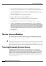
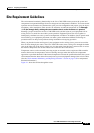
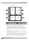
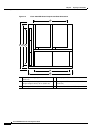
When you plan the location and layout of your equipment rack or wiring closet, you need to consider
how air flows through your router. The Cisco
7200 VXR routers draw cooling air in through the intake
vent on the right side of the chassis (when you view the router from the front), and move the air across
the internal components and out the exhaust vent on the left side of the chassis.
Temperature sensors on the network processing engine or network services engine and I/O controller
monitor the internal air temperature and send warning messages when the internal air temperature
approaches a specified threshold. If the internal temperature exceeds the specified threshold, the system
environmental monitor shuts down all internal power to prevent equipment damage from excessive heat.
(See the
“Environmental Monitoring and Reporting Functions” section on page 1-59 for temperature
threshold information.)
Figure 2-1 shows the airflow through the router.