


Chapter 3 Installing the Router
Supplemental Bonding and Grounding Connections
3-10
Cisco 12006 and Cisco 12406 Router Installation and Configuration Guide
OL-11497-03
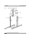
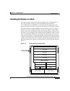
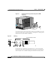
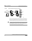
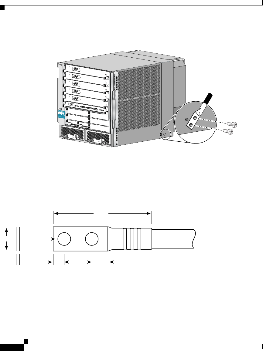
Figure 3-4 Supplemental Bonding and Grounding Port for NEBS
Compliance
Use a dual-hole lug to connect to the chassis with two 6.3-mm (M6) screws on the
0.63-inch (16-mm) centers as shown in
Figure 3-4 and Figure 3-5. The lug can be
ordered from Cisco (Part Number 32-0607-01).
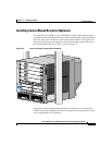
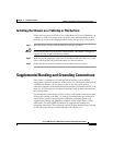
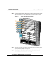
Figure 3-5 Cable Lug
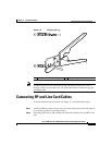
The dual-hole lug is crimped onto a grounding wire of a wire size and length
determined by your router location and facility environment. The crimping tool
shown in
Figure 3-6 is a standard crimping tool obtainable from many sources.
S
L
O
T
-0
GIGABIT ROUTE PR
OCESSO
R
S
L
O
T
-1
C
O
L
L
L
IN
K
T
X
R
X
R
J
-
4
5
M
II
R
E
S
E
T
AUX
E
J
E
C
T
C
O
N
S
O
L
E
CISCO 12000
S
E
R
I
E
S
G
I
G
A
B
I
T
S
W
I
T
C
H
R
O
U
T
E
R
57744
Crimp area
25527
2.24
0.48
0.08
0.25 0.370.63
End View
Ø 0.267
2 holes
All measurements in inches