


4-19
Cisco 12006 and Cisco 12406 Router Installation and Configuration Guide
OL-11497-03
Chapter 4 Troubleshooting the Installation
Problem Solving with Subsystems
DC-Input Power Entry Module LEDs
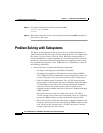
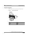
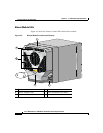
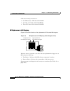
Figure 4-2 shows the location of the LEDs on the DC-input PEM.
Figure 4-2 DC-Input Power Entry Module LEDs
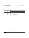
Table 4-7 summarizes the function of these indicators.
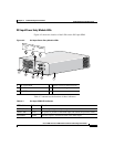
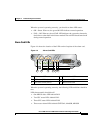
1 DC-input PEM 4 Captive screws on release levers
2 Handle 5 Air inlet for cooling fan
3 ON/OFF switch – –
62203
OUTPUT
OK
INPUT
OK
MISWIRE
OUTPUT
OK
INPUT
OK
MISWIRE
1
2
4
5
4
3
Ta b l e 4-7 DC-Input PEM LED Indicators
LED Label Color Function
OUTPUT OK Green PEM is operating normally in a powered-on condition.
INPUT OK Green DC power is present at the PEM input and within the specified limits.
MISWIRE Amber Indicates input is wired backward at the PDU input.