


4-21
Cisco 12006 and Cisco 12406 Router Installation and Configuration Guide
OL-11497-03
Chapter 4 Troubleshooting the Installation
Problem Solving with Subsystems
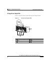
When the system is operating correctly, you should see these LED states:
• OK—Green. When on, the green OK LED indicates normal operation.
• FAIL—Off. When on, the red FAIL LED indicates the system has detected a
fan failure or other fault in the blower module.The red LED should remain off
during normal operation.
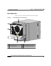
Alarm Card LEDs
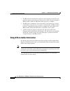
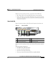
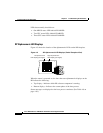
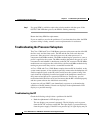
Figure 4-4 shows the location of the LEDs on the faceplate of the alarm card.
Figure 4-4 Alarm Card LEDs
When the system is operating correctly, the following LED conditions should be
true.
LEDs that normally should be off:
• One MBUS status LED labeled FAIL
• Two CSC status LEDs labeled FAIL
• Three SFC status LEDs labeled FAIL
• Three router alarm LEDs labeled CRITICAL, MAJOR, MINOR
1 MBus status LED 4 Critical alarm LED
2 CSC status LEDs (two) 5 Major alarm LED
3 SFC status LEDs (three) 6 Minor alarm LED
MBUS
CSC
ENABLED
FAIL
ALARM
0
SFC
CRITICAL
MAJOR
MINOR
01 1 2
1 432 5 6
66170