


3-38
Cisco CRS-1 Carrier Routing System SIP and SPA Hardware Installation Guide
OL-7113-05
Chapter 3 Overview: Cisco CRS-1 Shared Port Adapters
2-Port and 4-Port Clear Channel T3/E3 SPA Overview
2-Port and 4-Port Clear Channel T3/E3 SPA Cables and Connectors
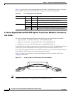
The interface connectors on the 2-Port and 4-Port Clear Channel T3/E3 SPA are 75-ohm coaxial Siemax
types, with one connector and cable for transmit (TX) and one for receive (RX).
The following cables can be used with the 2-Port and 4-Port Clear Channel T3/E3 SPA. The cables have
BNC connectors on one end and the Siemax connectors on the other. If similar SPAs are connected
back-to-back, both ends of cable will be Siemax.
• CAB-T3E3-RF-BNC-M (T3 or E3 Cable, 1.0/2.3 RF to BNC-Male, 10 feet)
• CAB-T3E3-RF-BNC-F (T3 or E3 Cable, 1.0/2.3 RF to BNC-Female, 10 feet)
• CAB-T3E3-RF-OPEN (T3 or E3 Cable, 1.0/2.3 RF to BNC-Open end, 10 feet)
Note The Cisco cable part numbers are 72-4124-01 (with male BNC end) and 72-4131-01 (with female BNC
end).
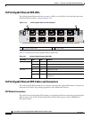
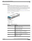
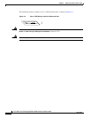
Figure 3-20 shows the connectors on the 4-Port Clear Channel T3/E3 SPA, and Table 3-29 describes the
signal descriptions for these connectors.
Ta b l e 3-29 2-Port and 4-Port Clear Channel T3/E3 SPA Connectors
Connector Label Meaning
TX Transmitted signals appear on the center contact, and the outer shield is ground
for the 75-ohm RG-59 coaxial cable you attach to the TX BNC connector.
RX Received signals appear on the center contact, and the outer shield is ground for
the 75-ohm RG-59 coaxial cable you attach to the RX BNC connector.