


5-6
Cisco CRS-1 Carrier Routing System SIP and SPA Hardware Installation Guide
OL-7113-05
Chapter 5 Installing and Removing a SIP
SIP Installation and Removal
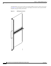
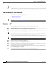
To install a SIP, see Figure 5-4 and follow these steps:
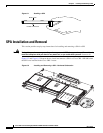
Step 1 Attach an ESD-preventive wrist strap and follow its instructions for use.
Step 2 Remove the SIP from its antistatic packaging.
Step 3 Remove the PLIM or PLIM impedance carrier from the slot you need to fill and set it aside.
Note Remove only one PLIM impedance carrier and install one SIP at a time. Be sure to verify that
each SIP is fully installed and secured before installing another card.
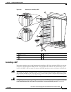
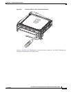
Step 4 Grasp one of the septums that separate the SPA slots or one of the ejector levers with one hand and place
your other hand under the SIP to support and guide it into the correct slot. Slide the card halfway into
the correct slot. Avoid touching the card circuitry or any connectors.
Step 5 Pivot both card ejector levers so the openings on the card ejector cams at the top and bottom of the SIP
pass over the tabs on each side of the card cage slot.
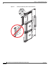
Caution Verify that the openings on the card ejector cams pass over the tabs; otherwise, one or both
ejector levers might bind when you attempt to close the ejector levers, thereby damaging or
breaking one or both ejector levers.
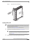
Step 6 Continue sliding the SIP into the card cage slot until the openings on the card ejector cams engage the
tabs on each side of the card cage slot.
Note Guide pins exist that make initial contact with the backplane connector as you slide a SIP into
its slot. After the guide pins make contact, continue pushing on the SIP until the card ejector
levers begin pivoting forward, toward the front panel on the SIP.
Step 7 To seat the card in the midplane connector, grasp both card ejector levers and pivot them inward toward
the handle in the card carrier until they are flush against the front edge of the card carrier.
Step 8 Engage both captive screws on the PLIM, and then tighten the screws.
Caution Be sure to engage both captive screws on the SIP before you begin to tighten the screws;
otherwise, the SIP might not seat properly.
Caution To ensure adequate space for additional PLIMs or SIPs, always tighten the captive screws on
each newly installed PLIM or SIP before you insert another one. These screws also prevent
accidental removal and provide proper grounding and EMI shielding for the system.
Step 9 Install the SPAs. See the “SPA Installation and Removal” section on page 6-2.
Step 10 Install the interface cables. We recommend that you clean the fiber-optic connections before attaching
the cables. See
Cisco CRS-1 Carrier Routing System Fiber-Optic Cleaning Guide for cleaning
instructions.