


5-4
Cisco CRS-1 Carrier Routing System SIP and SPA Hardware Installation Guide
OL-7113-05
Chapter 5 Installing and Removing a SIP
SIP Installation and Removal
Caution The router can indicate a hardware failure if you do not follow proper procedures. Remove or install only
one SIP or PLIM at a time. Wait at least 15 seconds before removing or installing another SIP or PLIM.
SIP Installation and Removal
This section contains the following procedures:
• Removing a SIP, page 5-4
• Installing a SIP, page 5-5
Note Refer to Chapter 6, “Installing and Removing a SPA,” for information on removing and installing SPAs.
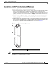
Removing a SIP
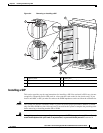
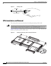
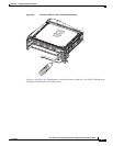
To remove a SIP from the line card chassis, see Figure 5-4 and follow these steps:
Step 1 Attach an ESD-preventive wrist strap and follow its instructions for use.
Step 2 Identify the card to be replaced and unplug the interface cables connected to the card. Be sure to note
the current connections of the cables to the ports on the SPAs installed in the SIP.
Warning
Because invisible radiation may be emitted from the aperture of the port when no fiber cable is
connected, avoid exposure to radiation and do not stare into open apertures.
Statement 125
Note You can also keep the dust caps or covers on the laser optical bores to avoid radiation exposure.
Step 3 Remove the SPAs from the SIP and set them aside.
Step 4 Loosen the two captive screws holding the SIP in place.
Step 5 Grasp the two card ejector levers and simultaneously pivot both ejector levers 90 degrees away from the
front edge of the card carrier to unseat the SIP from the backplane.
Step 6 Touching only the metal card carrier, slide the SIP from the slot and place it directly into an antistatic
sack or other ESD-preventive container.
Step 7 Insert another SIP, PLIM, or a PLIM impedance carrier into the empty card slot.