


6-7
Cisco CRS-1 Carrier Routing System SIP and SPA Hardware Installation Guide
OL-7113-05
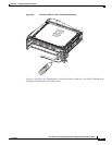
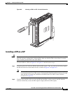
Chapter 6 Installing and Removing a SPA
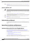
Checking the Installation
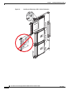
Cleaning Optical Devices
Any contamination of the fiber connection can cause failure of the component or failure of the whole
system. A particle that partially or completely blocks the core generates strong back reflections, which
can cause instability in the laser system. Inspection, cleaning, and reinspection are critical steps to take
before making fiber-optic connections.
For information on cleaning optical devices, refer to Cisco CRS-1 Carrier Routing System Fiber-Optic
Cleaning Guide.
Checking the Installation
This section describes the procedures you can use to verify the SIP and SPA installation and includes
information on the following topics:
• Verifying the Installation, page 6-7
• Using show Commands to Verify SIP and SPA Status, page 6-8
• Using show Commands to Display SPA Information, page 6-8
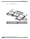
Verifying the Installation
This section describes how to verify the SIP and SPA installation by observing the SIP LED states, SPA
LED states, and the information displayed on the console terminal.
When the system has reinitialized all interfaces, the SIP LED should be green (on) and the SPA STATUS
LEDs should be green (on). The port LEDs may be green
(on), depending on your connections and
configuration. The console screen also displays a message as the system discovers each interface during
its reinitialization.
To verify that a SIP and SPA are installed correctly, follow these steps:
Step 1 Observe the console display messages and verify that the system discovers the SIP, while the system
reinitializes each interface, as follows:
• As a SIP is initialized, the LED is first amber, indicating that power is on, but the SIP is being
configured. When the SIP is active, the LED illuminates green.
• SPAs follow the same sequence after the SIP has completed its initialization. The SPA STATUS
LEDs illuminate amber, turning to green when the SPAs become active.
• When the SIP and SPA STATUS LEDs are green, all associated interfaces are configurable.
For configuration instructions, see Cisco IOS XR Interface and Hardware Component Configuration
Guide at the following URL:
http://www.cisco.com/univercd/cc/td/doc/product/ioxsoft/iox34/cgcr34/index.htm
• When a SIP or SPA is replaced with a module of the same type (as in an OIR or hardware swap), the
previous configuration is reinstated when the SIP or SPA becomes active.
• When a SIP or SPA has not been previously installed in the same slot or subslot, then the
configuration for all associated interfaces is empty.