


7-6
Cisco MDS 9000 Family NX-OS Interfaces Configuration Guide
OL-29284-01, Release 6.x
Chapter 7 Configuring N Port Virtualization
Information About N Port Virtualization
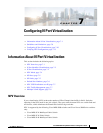
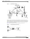
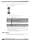
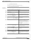
Figure 7-4 shows the internal FLOGI flows between an NPV core switch and an NPV device.
Figure 7-4 Internal FLOGI Flows
Table 7-1 identifies the internal FLOGI parameters that appear in Figure 7-4.
Although fWWN-based zoning is supported for NPV devices, it is not recommended because:
• Zoning is not enforced at the NPV device (rather, it is enforced on the NPV core switch).
• Multiple devices behind an NPV device log in via the same F port on the core (they use same fWWN
and cannot be separated into different zones).
• The same device might log in using different fWWNs on the core switch (depending on the NPV
link it uses) and may need to be zoned using different fWWNs.
Default Port Numbers
Port numbers on NPV-enabled switches will vary depending on the switch model. For details about port
numbers for NPV-eligible switches, see the Cisco NX-OS Family Licensing Guide.
NPV Core Switch
fc 5/10 fwwn
pwwn
nwwn
fc 1/5
NPV Device
184572
Ta b l e 7-1 Internal FLOGI Parameters
Parameter Derived From
pWWN The fWWN of the NP port.
nWWN The VSAN-based sWWN of the NPV device.
fWWN The fWWN of the F port on the NPV core switch.
symbolic port name The switch name and NP port interface string.
Note If there is no switch name available, then the output will display
“switch.” For example, switch: fc1/5.
IP address The IP address of the NPV device.
symbolic node name The NPV switch name.