


1-5
Cisco MWR 1900 Mobile Wireless Edge Router Hardware Installation Guide
78-13982-02
Chapter 1 Overview of the Cisco MWR 1900 Router
Compact Flash
Compact Flash
One external Compact Flash (CF) device is used on the MWR 1900 router. The CF memory size can vary
with a minimum size of 32Mbyte and a maximum size of 128Mbytes. This device is configured in
memory mapped mode (PCMCIA) to allow for hot insertion. This device is required for the MWR 1900
router to function because the IOS image and troubleshooting logs reside on this device. For information
about replacing or upgrading the CF, see the “Replacing or Upgrading the CF” section on page 3-10.
Overview of Cisco MWR 1900 Power Supplies
The MWR 1900 router is equipped with a +27 VDC power supply. The +27 VDC is typically used for
cell base stations.
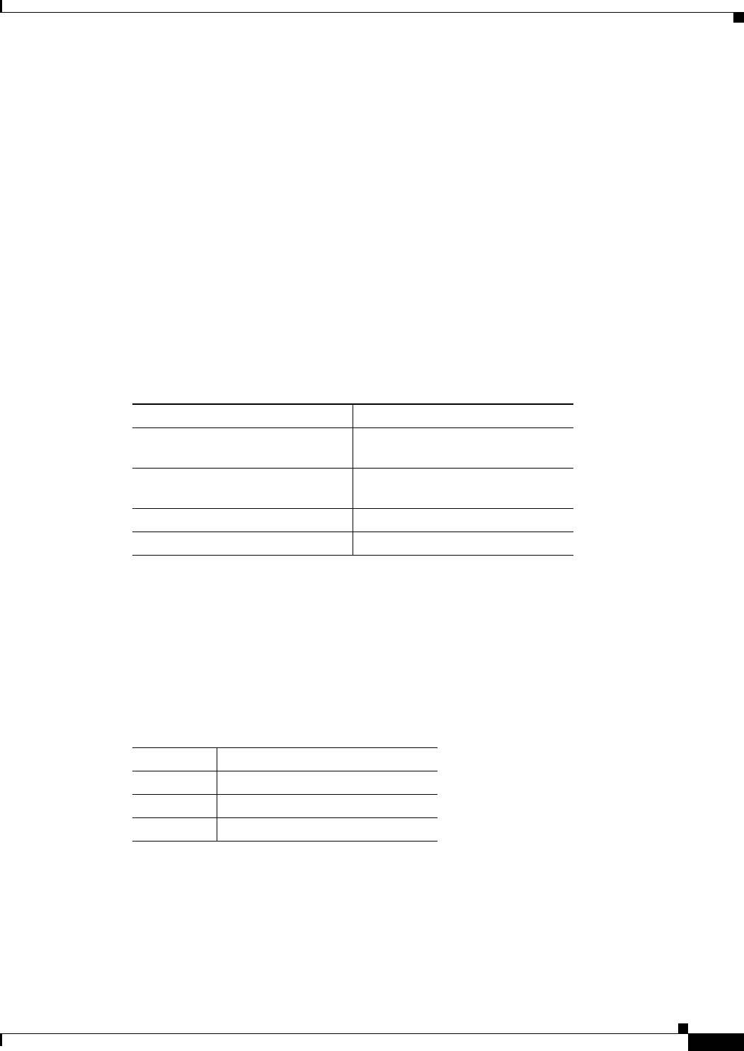
Table 1-1 lists DC power supply specifications of the Cisco MWR 1900 router.
Table 1-1 Cisco MWR 1900 Power Supply Specifications
2
Only solid copper conductors shall be used for the DC input power connection.
The Cisco MWR 1900 router uses a small, three-wire connector for the power supply. The connector on
the Cisco MWR 1900 router is Phoenix Contact part number 1754452 and should mated with Phoenix
Contact part number 1754465, which is attached to the power cable.
Table 1-2 lists the pinout configuration for the connector for both power supplies.
Table 1-2 Power Supply Connectors Pinout
Specification
+27 VDC
Input voltage, DC power supply
Maximum input current
+ 20 to 32 VDC
2.2A
Wire gauge for DC-input power
connections
2
18 AWG
Power Dissipation 44 W (typical)
Power Output 35 W (typical)
PIN
+27 VDC Power Supply
1 + 27 VDC
2 Ground
3RTN