


3-7
Cisco MWR 1900 Mobile Wireless Edge Router Hardware Installation Guide
78-13982-02
Chapter 3 Installing the Router
Connecting the MWR 1900 Router to a DC-Input Power Supply
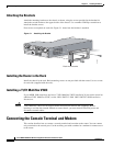
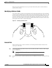
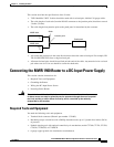
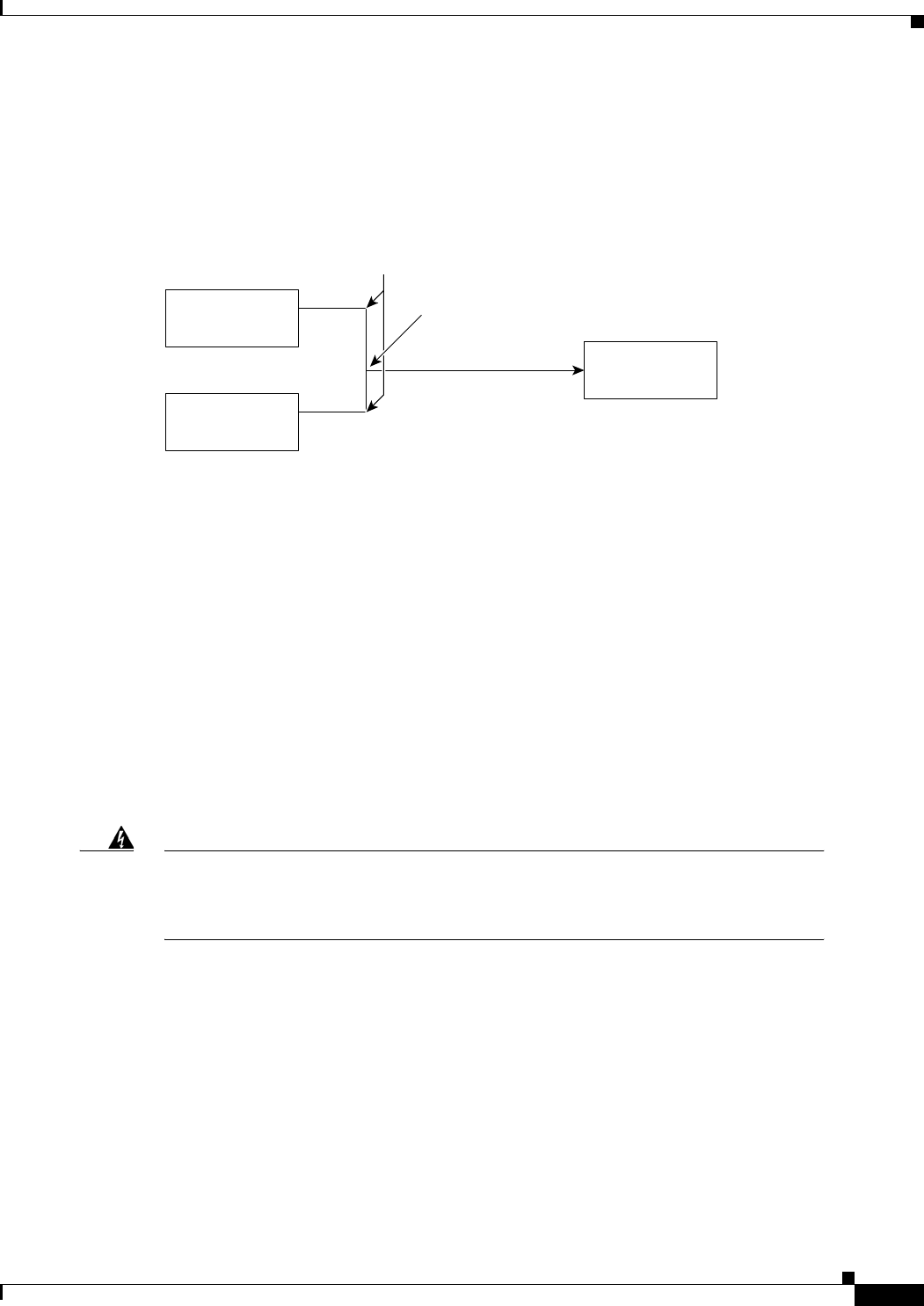
This section describes the specifications of the Y-cable.
• T1/E1 Multiflex VWIC Y-cables should be made with 4 twisted-pair, shielded, 28-gauge cables.
• The cable length of each stub (from the RJ-48C connector to the junction point) should not exceed
3 inches (76 mm).
• The cable length from junction point to the patch panel is determined by the customer.
• All signals that propagate in the same direction must share the same twisted pair. For example, RX
TIP and RX RING must form a single twisted pair.
• All unused twisted pairs should be cut flush on both ends of the cable. Any unused wire in a twisted
pair where one wire is in use should be cut flush at both ends.
Connecting the MWR 1900 Router to a DC-Input Power Supply
This section contains instructions for:
• Required Tools and Equipment
• Grounding the Router
• Wiring the DC-Input Power Source
• Powering On the Router
Warning
This unit is intended for installation in restricted access areas. A restricted access area
is where access can only be gained by service personnel through the use of a special
tool, lock and key, or other means of security, and is controlled by the authority
responsible for the location.
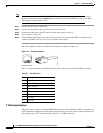
Required Tools and Equipment
You need the following tools and equipment:
• Terminal block connector (Phoenix part number 1754465).
• Ratcheting torque screwdriver with a Phillips head that exerts up to 15 pound-force inches (lbf-in)
of pressure.
• Panduit crimping tool with optional controlled cycle mechanism, model CT-700, CT-720, CT-920,
CT-930, CT-920CH, or CT-940CH.
• 6-gauge copper ground wire (insulated or noninsulated).
Stubs
Y- C a b l e
Patch panel
Junction point
MWR 1900
MWR 1900
65826
E1/
T1
E1/
T1