


3-9
Cisco MWR 1900 Mobile Wireless Edge Router Hardware Installation Guide
78-13982-02
Chapter 3 Installing the Router
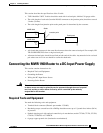
Connecting the MWR 1900 Router to a DC-Input Power Supply
Step 6 Use the screw to attach the ground lug and wire assembly to the rear panel of the switch.
Step 7 Using a ratcheting torque screwdriver, torque the ground-lug screw to 15 1bf-in (or 240 ounce-force
inches [240 ozf-in]).
Wiring the DC-Input Power Source
Warning
This product relies on the building’s installation or power supply for short circuit
(overcurrent) protection. Ensure that a listed and certified fuse or circuit breaker no
larger than 60 VDC, 15A U.S. is used on all current-carrying conductors.
Note The installation must comply with the 1996 National Electric Code (NEC) and other
applicable codes.
To connect the DC power supply to the Cisco MWR 1900 router, do the following:
Step 1 Turn OFF the DC power source at the circuit breaker and tape the circuit breaker in the OFF position.
Step 2 Connect one end of the customer-supplied power cord (18-AWG copper wire) to the DC power source.
Step 3 Attach the terminal block connector (Phoenix part number 1754465) to the other end of the power supply
cord. Ensure that the pinouts are configured properly. The pinouts are listed on the label beside the power
connector on the back of the MWR 1900 router.
Step 4 Plug the connector on the power supply cord into the MWR 1900 power supply connector, which is the
green connector on the right-hand side of the back of the MWR 1900 router.
Warning
An exposed wire lead from a DC-input power source can conduct harmful levels of
electricity. Be sure that no exposed portion of the DC-input power source wire extends
from the terminal block plug.
Warning
Secure all power cabling when installing this unit to avoid disturbing field-wiring
connections.
Powering On the Router
Warning
The plug-socket combination must be accessible at all times because it serves as the
main disconnecting device.