


3-6
Cisco MWR 1900 Mobile Wireless Edge Router Hardware Installation Guide
78-13982-02
Chapter 3 Installing the Router
Connecting the Network Cables
Note If you choose to use the T1/E1 Multiflex VWIC in a non-redundant configuration, you must close
the relays on the card using the standalone subcommand. For more information, see the “Cisco MWR
1900 Software Configuration Guide.”
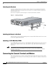
Step 1 Confirm that the router is turned off.
Step 2 Connect one end of the cable to the T1 or E1 port on the card.
Step 3 Connect the other end to the BTS patch or demarcation panel at your site.
Step 4 Turn on power to the router.
Step 5 Check that the CD LED goes on, which means that the card’s internal CSU/DSU is communicating
with the CSU/DSU at the T1 or E1 service provider central office.
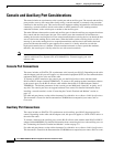
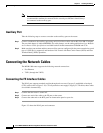
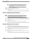
The T1/E1 Multiflex VWIC uses an RJ-48C connection, as shown in Figure 3-4.
Figure 3-4 RJ-48C Connection
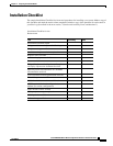
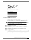
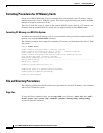
Table 3-2 shows the pinout configuration of the RJ-48C connectors on the T1/E1 Multiflex VWIC.
Table 3-2 RJ-48C Pinout
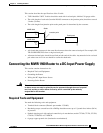
Y-Cable Specifications
Although it can be used in a standalone MWR 1900 router, the T1/E1 Multiflex VWIC is designed to be
used in redundant configurations. Such configurations require a special Y-cable for connecting the active
and standby routers. The Y-cable provides a dual E1 or T1 PRI connection.
24939
8 7 6 5 4 3 2 1
RJ-48C connector
Pin Description
1 receive tip
2 receive ring
3 receive shield
4transmit tip
5 transmit ring
6 transmit shield
7 not used
8 not used