


3-4
Cisco MWR 1900 Mobile Wireless Edge Router Hardware Installation Guide
78-13982-02
Chapter 3 Installing the Router
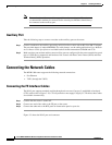
Connecting the Network Cables
Note Because hardware flow control is not possible on the console port, Cisco does not
recommend that modems be connected to the console port. Modems should always
be connected to the auxiliary port.
Auxiliary Port
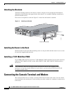
Take the following steps to connect a modem to the auxiliary port on the router:
Step 1 Connect a modem to the auxiliary port using an RJ-45 rollover cable with an RJ-45-to-DB-25 adapter.
The provided adapter is labeled MODEM. For cable pinouts, see the online publication Cisco Modular
Access Router Cable Specifications available both on the Documentation CD-ROM and CCO.
Step 2 Make sure that your modem and the router auxiliary port are configured for the same transmission speed
(up to 115200 bps is supported) and hardware flow control with Data Carrier Detect (DCD) and Data
Terminal Ready (DTR) operations.
Connecting the Network Cables
The MWR 1900 router supports the following network connections:
• Fast Ethernet
• T1/E1 (through the VWIC)
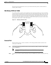
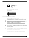
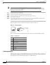
Connecting the FE Interface Cables
The RJ-45 port supports standard straight-through and crossover Category 5 unshielded twisted-pair
(UTP) cables (refer to Figure 3-15). Cisco Systems does not supply Category 5 UTP cables; these cables
are available commercially.
Step 1 Confirm that the router is turned off.
Step 2 Connect one end of the cable to the FE port on the router.
Step 3 Connect the other end to the BTS patch or demarcation panel at your site.
Figure 3-3 shows the RJ-45 port and connector.