


2-4
Cisco Integrated Services Router Hardware Installation Guide
OL-27407-01
Chapter 2 Installing the Router
Installing the Cisco 810 ISR
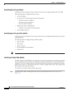
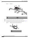
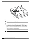
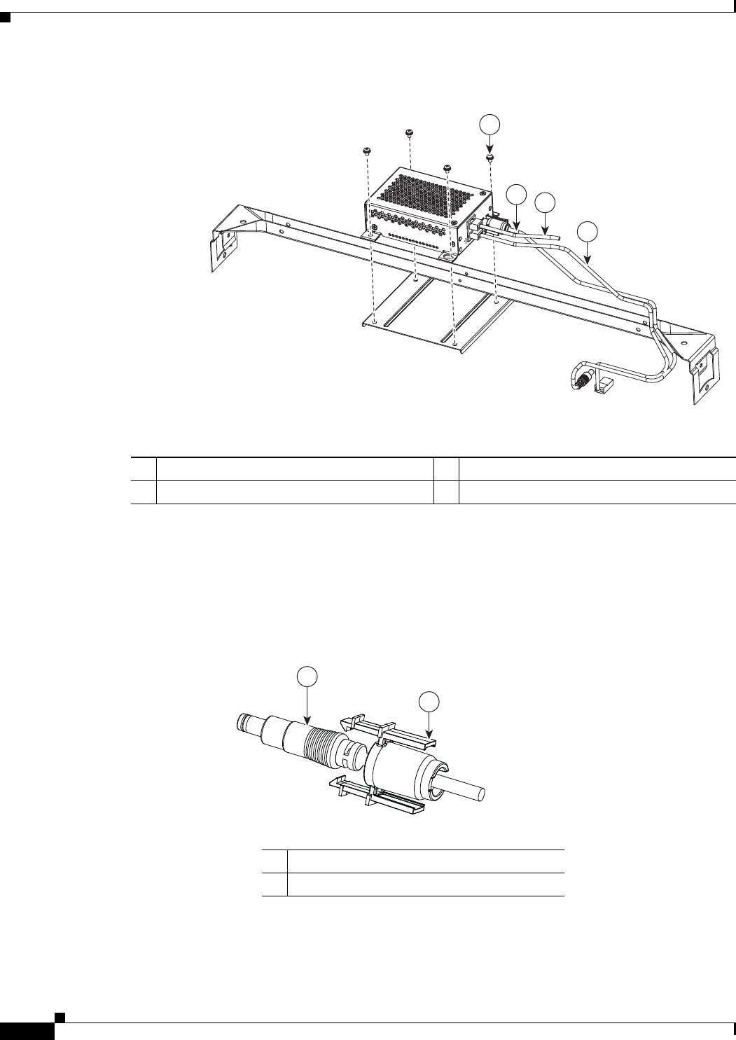
Figure 2-2 6-32 Screws
Step 3 Connect the supplied plenum rated Cat5 cable to the GE0 port on the PoE+ splitter.
Step 4 Connect the Cat5 cable from your PoE+ source to the PoE+ in port on the PoE+ splitter.
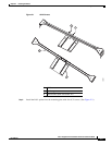
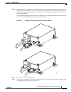
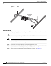
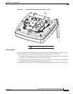
Step 5 Place the power cord lock onto the power cord behind the connector overmold as shown in Figure 2-3.
Slide the power cord lock forward so that it captures the overmold and is fully seated.
Figure 2-3 Placement of the Power Cord Lock onto the Power Cord
285668
1
2
3
4
1 6-32 screws 3 To PoE+ power source
2 Power cable with power cord lock installed 4 GE CAT5 cable
345076
1
2
1 Power cord connector
2 Power cord lock