


2-17
Cisco Integrated Services Router Hardware Installation Guide
OL-27407-01
Chapter 2 Installing the Router
Installing the Cisco 810 ISR
Step 3 (Optional) Drill or cut a cable access hole near and below the location of the mounting bracket cable
access cover large enough for the Ethernet cable, building ground wire, and power cables.
Step 4 Pull approximately 9 inches of cable through the hole.
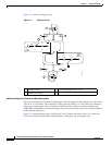
Step 5 Route the Ethernet and power cables through the bracket before you attach the bracket to the ceiling or
wall.
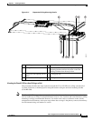
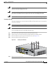
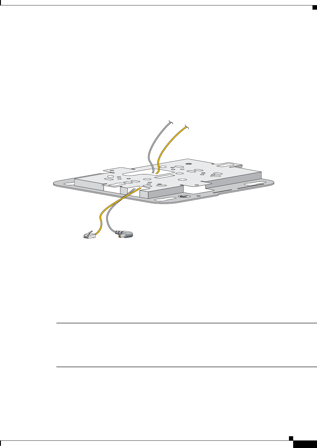
Step 6 Route the cables through the main cable access hole and then through the smaller access hole as shown
in Figure 2-16.
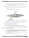
Figure 2-16 Routing the Ethernet and Power Cables
Step 7 (Optional) Use the ground screw to attach the building ground wire to the ground location on the base
of the router. See the “Grounding the Cisco 812 ISR” section on page 2-18 for the general grounding
instructions.
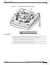
Step 8 Position the mounting bracket mounting holes (with indents down) over the pilot holes.
Step 9 Insert a fastener into each mounting hole and tighten.
Step 10 Connect the Ethernet and power cables to the router.
Step 11 Align the router feet with the large part of the keyhole mounting slots on the mounting plate.
Step 12 Gently slide the router onto the mounting bracket keyhole slots until it clicks into place.
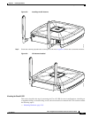
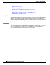
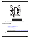
Mounting the Cisco 812 ISR to a Network or Electrical Box
To mount the Cisco 812 ISR to a network box or an electrical box, perform these steps:
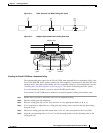
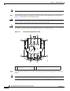
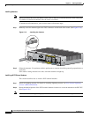
Step 1 Position the universal mounting bracket (C810-BR-CM) over the existing network or electrical box and
align the bracket mounting holes with the box holes.
Step 2 Hold the mounting bracket in place and insert a 6-32 x 0.18-inch pan head screw into each of the
mounting holes and tighten.
Step 3 Pull approximately 9 inches of Ethernet and power cable through the hole.
344775