


2-5
Cisco Integrated Services Router Hardware Installation Guide
OL-27407-01
Chapter 2 Installing the Router
Installing the Cisco 810 ISR
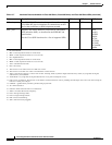
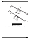
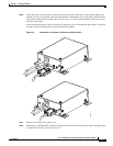
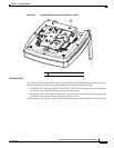
Step 6 Install the power cord with power cord lock to the power jack of the PoE+ splitter while making sure
that the two arms of the power cord lock slide into the corresponding slots on the PoE+ splitter and are
fully seated with both arms locking into the slots. Figure 2-4 shows the installation of the power cord
lock and other cables.
In the event that the power cord lock needs to be removed, user your thumb and index fingers to squeeze
the ends of the tabs while pulling away from the PoE+ splitter.
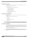
Figure 2-4 Installation of the Power Cord Lock and Other Cables
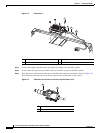
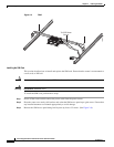
Step 7
Remove one ceiling tile to gain access.
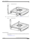
Step 8 Install the pre-assembled rail with PoE+ splitter into the T-rail. Push down the box hanger mounting clips
to lock into the T-rail as shown in Figure 2-5.
345075