


3-7
Cisco Integrated Services Router Hardware Installation Guide
OL-23125-02
Chapter 3 Connecting the Router
Cisco 810 Series
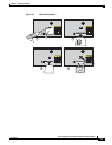
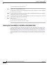
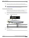
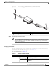
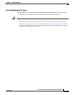
Figure 3-6 DC Power Supply PWR2-20W-12VDC and PWR2-20W-24VDC
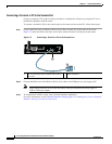
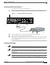
Step 2
Plug the adapter cord into the router.
Note The power adapters have 18 AWG wires for the input connection. Tinned bare wires are used for
the input connection as there is no standard established for connector type. Screw terminal
blocks are most often used.
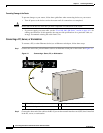
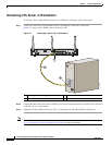
Verifying Connections
To verify that all devices are properly connected to the router, first turn on all the connected devices,
then check the LEDs. To verify router operation, refer to Table 3-1.
For full LED description, see Table 1-29.
302438
3
2
1
1 Black wire (negative) 3 Adapter
2 White wire (positive)
Table 3-1 Verifying the Router Operation
Power and Link LEDs to Check Normal Patterns
SYS Yellow FPGA download is complete.
Green (blinking) ROMMON is operational.
Off After powering up, when FPGA is being downloaded (in
ROMMON).