


2-33
Cisco Integrated Services Router Hardware Installation Guide
OL-27407-01
Chapter 2 Installing the Router
Installing the Cisco 810 ISR
Installing the Router Ground Connection
The router must be connected to a reliable earth ground. Install the ground wire in accordance with local
electrical safety standards.
• For NEC-compliant grounding, use size 14 AWG (2 mm2) or larger copper wire and a ring terminal
with an inner diameter of 1/4 in. (5 to 7 mm).
• For EN/IEC 60950-compliant grounding, use size 18 AWG (1 mm2) or larger copper wire.
Warning
This equipment needs to be grounded. Use a green and yellow 12 to 14 AWG ground wire to connect
the host to earth ground during normal use.
Statement 242
To install the ground connection, follow these steps:
Step 1 Strip one end of the ground wire to the length required for the terminal.
Step 2 Crimp the ground wire to the ring terminal using the wire crimper.
Step 3 If you choose to install the power switch lock, perform Step 5 to Step 7. Otherwise, perform Step 4,
Step 6 and Step 7.
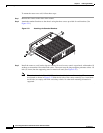
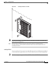
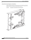
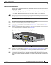
Step 4 Attach the ring terminal to the chassis. Use the single screw provided. Tighten the screws to a torque of
8 to 10 inch-pound (0.9 to 1.1 newton meter). (See Figure 2-29.)
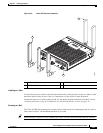
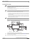
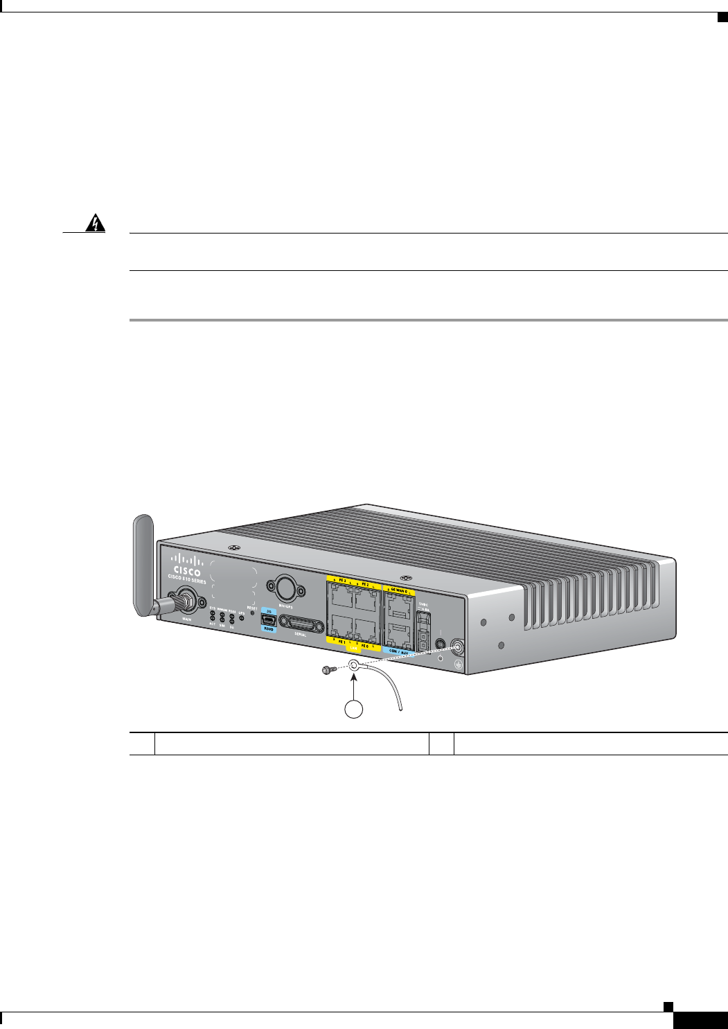
Figure 2-29 Chassis Ground Connection Using Ring Terminal
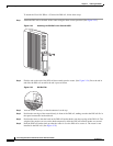
Step 5
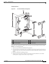
Install the power switch lock, see the “Installing the Power Switch Lock” section on page 2-35. Tighten
the screws to a torque of 8 to 10 in-lb (0.9 to 1.1 N-m). Torque the hex standoff to the same torque.
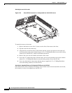
Step 6 Connect the other end of the ground wire to a known reliable earth ground point at your site.
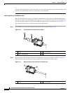
Step 7 If you are using this router in a vehicle, attach the ring terminal to the chassis using one of the screws
provided and the green or green and yellow striped wire. Connect the other end of the wire to the vehicle
ground.
1 Ring terminal
245828
1