


11
Cisco XR 12000 Series Router Ethernet Line Card Installation
OL-7861-01
Removing and Installing a Line Card
• After you reinstall a line card, the router automatically downloads the necessary software from the
route processor (RP). Next, the router brings online only those interfaces that match the current
configuration and were previously configured as administratively up. You must configure all others
with the configure command.
Caution The router may indicate a hardware failure if you do not follow proper procedures. Remove
or insert only one line card at a time. Allow at least 15 seconds for the router to complete the
preceding tasks before removing or inserting another line card.
After removing and inserting a line card into the same slot, allow at least 60 seconds before
removing or inserting another line card.
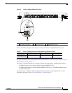
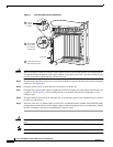
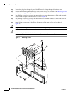
• Line cards have two ejector levers to release the card from its backplane connector. Use the levers
when you are removing the line card and to seat the line card firmly in its backplane connector when
you are installing the line card. The ejector levers align and seat the card connectors in the
backplane.
Caution When you remove a line card, always use the ejector levers to ensure that the connector pins
disconnect from the backplane in the sequence expected by the router. Any card that is only
partially connected to the backplane can halt the router.
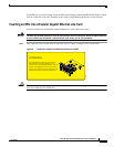
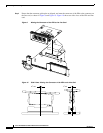
When you install a line card, always use the ejector levers to ensure that the card is correctly
aligned with the backplane connector; the connector pins should make contact with the
backplane in the correct order, indicating that the card is fully seated in the backplane. If a
card is only partially seated in the backplane, the router will hang and subsequently crash.
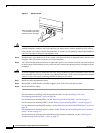
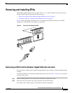
Removing a Line Card
If you are replacing a failed line card, remove the existing line card first, then install the new line card
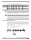
in the same slot. To remove a line card, use Figure 4 as a reference and follow these steps:
Step 1 Attach an ESD-preventive wrist or ankle strap and follow its instructions for use.
Step 2 Disconnect and remove all interface cables from the ports; note the current connections of the cables to
the ports on the line card.
Step 3 Detach the line card cable-management bracket from the line card.
Step 4 Use a screwdriver to loosen the captive screw at each end of the line card faceplate. (See Figure 4a.)