


14
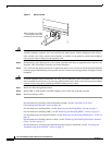
Cisco XR 12000 Series Router Ethernet Line Card Installation
OL-7861-01
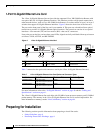
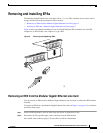
Removing and Installing a Line Card
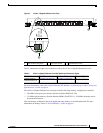
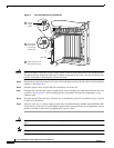
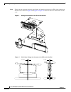
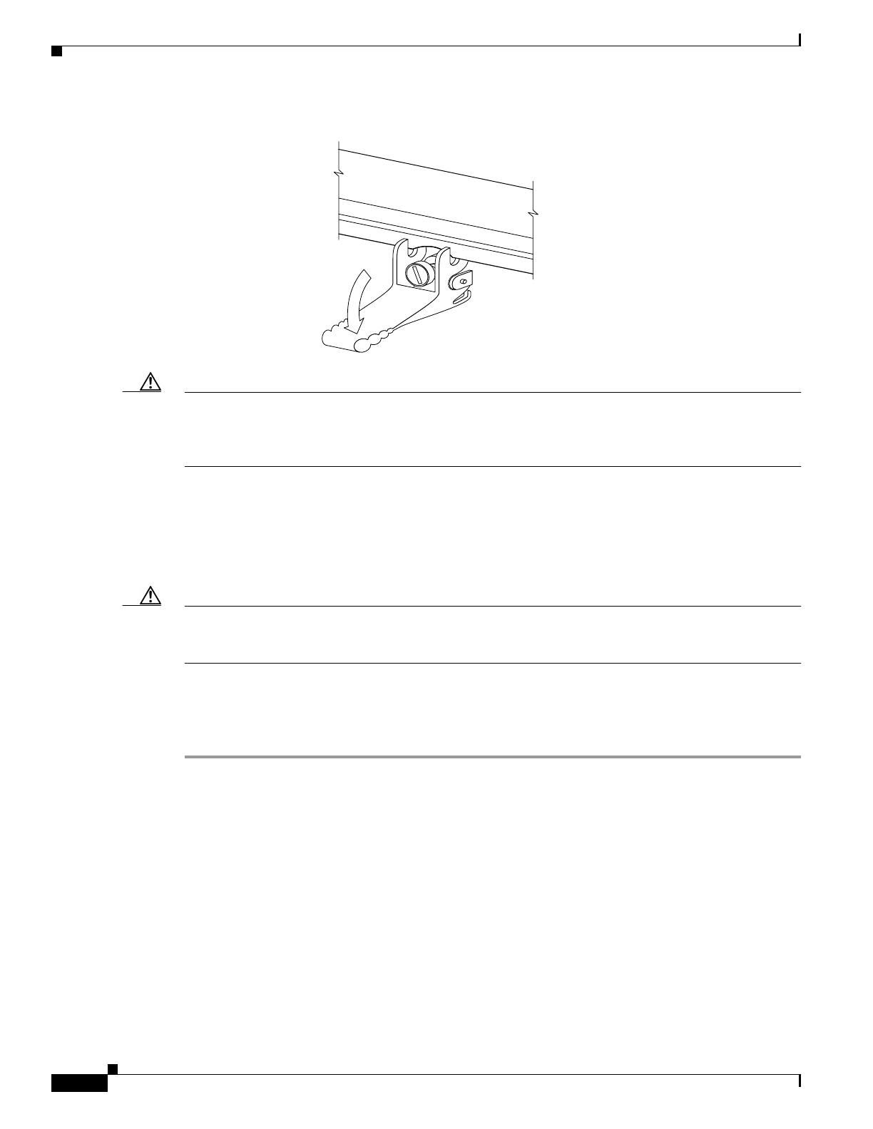
Figure 5 Ejector Levers
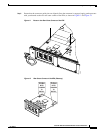
Caution When you install a line card, always use the ejector levers to ensure that the card is correctly aligned
with the backplane connector, the card connector pins make contact with the backplane in the correct
order, and the card is fully seated in the backplane. A card that is only partially seated in the backplane
can cause the router to hang and subsequently crash.
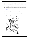
Step 5 Simultaneously pivot both ejector levers toward each other until they are perpendicular to the line card
faceplate. This action firmly seats the card in the backplane.
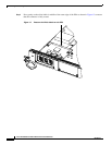
Step 6 Use a 3/16-inch flat-blade screwdriver to tighten the captive screw on each end of the line card faceplate
to ensure proper EMI shielding and to prevent the line card from becoming partially dislodged from the
backplane.
Caution To ensure adequate space for additional line cards, always tighten the captive installation screws on each
newly installed line card before you insert any additional line cards. These screws also prevent accidental
removal and provide proper grounding and EMI shielding for the router.
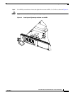
Step 7 Install the cable-management bracket.
Step 8 Install GBIC or SFP modules, and EPA daughter cards, in the line cards that use them.
Step 9 Install the interface cables.
For information on installing cable-management brackets, see the “Installing a Line Card
Cable-Management Bracket” section on page 40.
For information on installing EPAs, see the “Removing and Installing EPAs” section on page 15.
For information on installing GBICs, see the “Removing and Installing GBICs” section on page 22.
For information on installing SFP modules, see the “Removing and Installing SFP Modules” section on
page 25.
For information on installing interface cables, see the “Removing and Installing Fiber-Optic Interface
Cables” section on page 51.
For information on verifying and troubleshooting the hardware installation, see the “Verifying and
Troubleshooting the Installation” section on page 57.
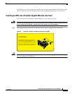
When inserting a card, make
sure the ejector lever hooks
catch the lip of the card cage.
H7681