


56
Cisco XR 12000 Series Router Ethernet Line Card Installation
OL-7861-01
Cabling and Specifications
Step 1 Use a lint-free tissue soaked in 99 percent pure isopropyl alcohol and gently wipe the end-face of the
fiber core. Wait 5 seconds for the surfaces to dry and wipe the surfaces a second time.
Step 2 Use clean, dry, oil-free compressed air to remove any residual dust from the connector.
Warning
Invisible laser radiation can be emitted from the aperture of the port when no cable is connected.
Avoid exposure to laser radiation and do not stare into open apertures.
Step 3 Use a magnifying glass or inspection microscope to inspect the ferrule at angle. Do not look directly into
the aperture. If you detect any contamination, repeat Step 1 and Step 2.
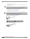
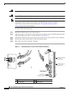
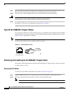
Type RJ-45 100BASE-T Copper Cables
For an 8-Port Fast Ethernet line card with RJ-45 ports, use an EIA/TIA–568-compliant cable with MDI
wiring and RJ-45 connectors to connect your Cisco XR 12000 Series Router to another router or switch.
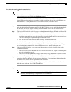
Figure 43 shows a typical RJ-45 connector.
Note EIA/TIA–568-compliant cable with MDI wiring and RJ-45 connectors are available from a wide variety
of sources. These cables are not available from Cisco Systems.
Figure 43 RJ-45 Cable Connector
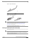
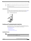
Removing and Installing RJ-45 100BASE-T Copper Cable
This section contains information on removing and installing RJ-45 copper cables to connect your router
to another router or switch.
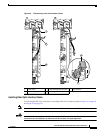
Removing RJ-45 Cables
To remove line card cables, follow these steps (refer to Figure 44 on page 57):
Step 1 Attach an ESD-preventive wrist or ankle strap to your wrist and follow its instructions for use.
Step 2 Disconnect the interface cable connectors from the line card interface ports.
Note You do not have to remove the interface cables from the line card cable-management bracket.
H2936
8 7 6 5 4 3 2 1
RJ-45 connector