


15-18
Cisco ONS 15310-CL, ONS 15310-MA, and ONS 15310-MA SDH Ethernet Card Software Feature and Configuration Guide, R9.1 and R9.2
78-19415-01
Chapter 15 Configuring Resilient Packet Ring on the ML-Series Card
Add an ML-Series Card into an RPR
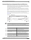
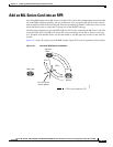
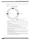
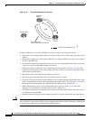
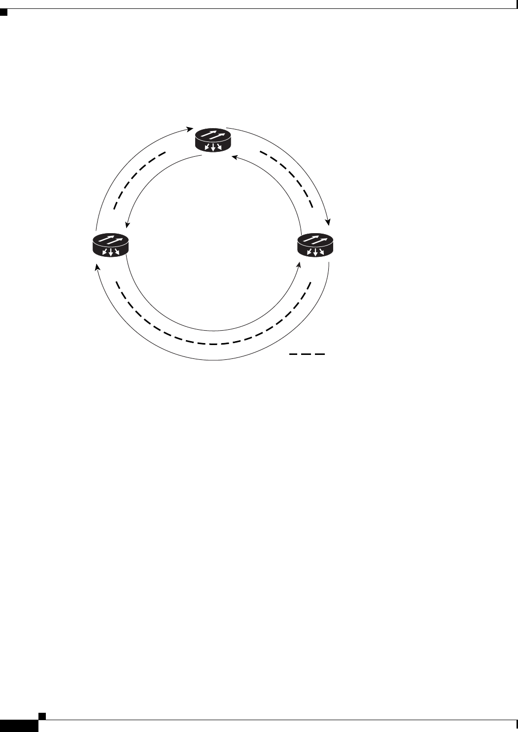
Figure 15-8 shows the RPR after the third node is added with the two new STS circuits and spans that
will be added.
Figure 15-8 Three-Node RPR After the Addition
To add an ML-Series card to the RPR, you need to complete several general actions:
•
Force away any existing non-ML-Series card circuits, such as DS-1, that use the span that will be
deleted.
•
Shut down the POS ports on the adjacent ML-Series cards for the STS circuit that will be deleted to
initiate the RPR wrap.
•
Test Ethernet connectivity between the access ports on the existing adjacent ML-Series cards with
a test set to ensure that the RPR wrapped successfully.
•
Delete the STS circuit that will be replaced by the new circuits. (In Figure 15-7, this is the circuit
between Adjacent Node 2, POS 0 and Adjacent Node 1, POS 1.)
•
Insert the new node into the ring topology if the node is not already part of the topology.
•
Install the ML-Series card and load your initial configuration file or otherwise do an initial
configuration of the ML-Series card.
•
Ensure the new node is configured with RPR before its POS ports are manually enabled or enabled
through the configuration file.
•
Create an STS circuit from one of the POS ports of an existing adjacent ML-Series card to a POS
port on the new ML-Series card. (In Figure 15-8, this is the circuit between Adjacent Node 2,
POS Port 0 and New Node, POS Port 1.)
•
Create a second STS circuit from one of the POS ports of the other existing adjacent ML-Series card
to the remaining POS port on the new ML-Series card. (In Figure 15-8, this is the circuit between
New Node, POS Port 0 and Adjacent Node 1, POS Port 1.)
SPR 1
POS 1 POS 0
POS 0
POS 0
POS 1
POS 1
= STS circuit created on CTC
Adjacent Node 2
Adjacent Node 1
New Node
145991