


15-19
Cisco ONS 15310-CL, ONS 15310-MA, and ONS 15310-MA SDH Ethernet Card Software Feature and Configuration Guide, R9.1 and R9.2
78-19415-01
Chapter 15 Configuring Resilient Packet Ring on the ML-Series Card
Add an ML-Series Card into an RPR
•
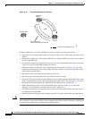
Configure the new ML-Series card to join the RPR and enable the POS ports, if the initial
configuration file did not already do this.
•
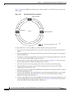
Enable the POS ports on the existing adjacent ML-Series cards that connect to the new ML-Series
card. (In Figure 15-8, these are Adjacent Node 1, POS Port 1 and Adjacent Node 2, POS Port 0.)
•
Test Ethernet connectivity between the access ports on the new ML-Series card with a test set to
validate the newly created three-node RPR.
•
Monitor Ethernet traffic and existing routing protocols for at least an hour after the node insertion.
Caution
The specific steps in the following procedure are for the topology in the example. Your own steps will
vary according to your network design. Do not attempt this procedure without obtaining a detailed plan
or method of procedure from an experienced network architect.
Adding an ML-Series Card into an RPR
To
add an ML-Series card to the RPR in the example, complete the following procedure:
Step 1
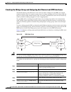
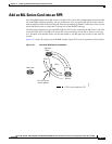
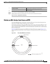
Start a Cisco IOS CLI session for the ML-Series card in the first adjacent node. This is Adjacent Node
1 in Figure 15-7.
Step 2
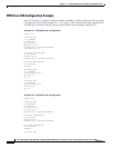
Complete the following Cisco IOS configuration on the ML-Series card in the first adjacent node,
beginning in global configuration mode:
Step 3
Start a Cisco IOS CLI session for the ML-Series card in Adjacent Node 2, as shown in Figure 15-7.
Step 4
Complete the following Cisco IOS configuration on the Adjacent Node 2 ML-Series card, beginning in
global configuration mode:
Step 5
In CTC, log into Adjacent Node 1.
Step 6
Double-click the ML-Series card in Adjacent Node 1.
The card view appears.
Step 7
Click the Circuits tab.
Step 8
Click the Circuits subtab.
Step 9
Identify the appropriate STS circuit by looking under the source column and destination column for the
circuit entry that matches the POS ports at the endpoints of the circuit to be deleted.
The circuit entry is in node-name/card-slot/port-number format, such as Node-1/s12(ML100T)/pPOS-0.
Step 10
Click the circuit entry to highlight it.
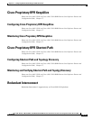
a.
Router(config)# interface pos
interface-number
Enters interface configuration mode for the POS port at one
endpoint of the circuit to be deleted.
b.
Router(config-if)# shutdown
Closes the interface, which initiates the RPR wrap.
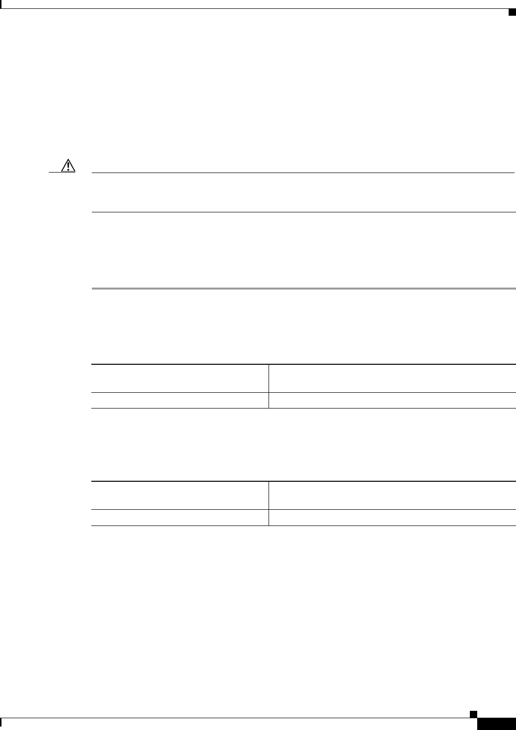
a.
Router(config)# interface pos
interface-number
Enters interface configuration mode for the POS port at one
endpoint of the circuit to be deleted.
b.
Router(config-if)# shutdown
Closes the interface.