


15-22
Cisco ONS 15310-CL, ONS 15310-MA, and ONS 15310-MA SDH Ethernet Card Software Feature and Configuration Guide, R9.1 and R9.2
78-19415-01
Chapter 15 Configuring Resilient Packet Ring on the ML-Series Card
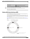
Delete an ML-Series Card from an RPR
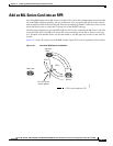
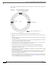
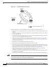
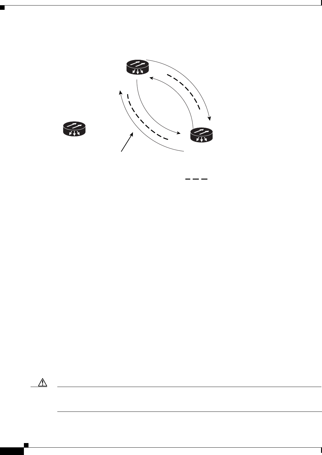
Figure 15-10 Two-Node RPR After the Deletion
To delete an ML-Series card from the RPR, you need to complete several general actions:
•
Force away any existing non-ML-Series card circuits, such as DS-1, that use the spans that will be
deleted.
•
Shut down the POS ports on the adjacent ML-Series cards for the STS circuits that will be deleted
to initiate the RPR wrap.
•
Test Ethernet connectivity between the access ports on the existing adjacent ML-Series cards with
a test set to ensure that the RPR wrapped successfully.
•
Delete the two STS circuits that will be replaced by the new circuits. (In Figure 15-9, this is the
circuit between the Delete Node and one Adjacent Node, and the circuit between the Delete Node
and the other Adjacent Node.)
•
Remove the Delete Node from the ring topology if desired.
•
Physically remove the delete ML-Series card from the node if desired.
•
Create an STS circuit from the available POS port of one of the remaining adjacent ML-Series cards
to the available POS port on the other remaining adjacent ML-Series card. (In Figure 15-10, this is
the circuit between Adjacent Node 2, POS Port 0 and Adjacent Node 1, POS Port 1.)
•
Enable the POS ports on the existing adjacent ML-Series cards.(In Figure 15-10, this is the
Adjacent Node 2, POS Port 0 and the Adjacent Node 1, POS Port 1.)
•
Test Ethernet connectivity between the access ports on the adjacent ML-Series card with a test set
to validate the two-node RPR.
•
Monitor Ethernet traffic and existing routing protocols for at least an hour after the node deletion.
Caution
The specific steps in the following procedure are for the topology in the example. Your own steps will
vary according to your network design. Do not attempt this procedure without obtaining a detailed plan
or method of procedure from an experienced network architect.
SPR 1
POS 1
POS 0
POS 0
POS 1
= STS circuit created on CTC
Adjacent
Node 2
Adjacent
Node 1
This STS circuit
was created after the deletion.
Deleted Node
145993