


Overview 1-7
Receptacles, Cables, and Pinouts
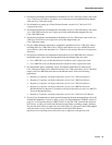
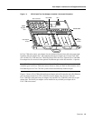
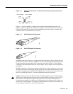
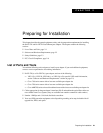
Figure 1-10 Crossover Cable Pinout—PA-FE-TX RJ-45 Connections Between Hubs and
Repeaters
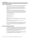
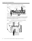
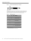
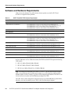
Figure 1-11 shows the duplex SC connector (one required for both transmit and receive), and
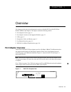
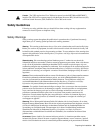
Figure 1-12 shows the simplex SC connector (two required, one for each transmit and receive) used
for PA-FE-FX optical-fiber connections. These multimode optical-fiber cables are commercially
available, and are not available from Cisco Systems.
Figure 1-11 PA-FE-FX Duplex SC Connector
Figure 1-12 PA-FE-FX Simplex SC Connector
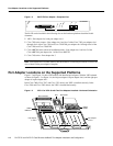
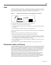
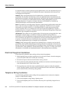
Depending on the type of media you use between the MII connection on the port adapter and your
switch or hub, the network side of your100BaseT transceiver should be appropriately equipped with
ST-type connectors (for optical fiber), BNC connectors, and so forth. Figure 1-13 shows the pin
orientation of the female MII connector on the port adapter. The port adapters are field-replaceable
units (FRUs).
The MII receptacle uses 2-56 screw-type locks, called jackscrews (shown in Figure 1-13), to secure
the cable or transceiver to the MII port. MII cables and transceivers have knurled thumbscrews that
you fasten to the jackscrews on the PA-FE-TX’s MII connector.Use the jackscrews to provide strain
relief for your MII cable. Figure 1-13 shows the MII female connector (receptacle).
Caution Before you attach your MII transceiver to the MII receptacle on your PA-FE port adapter,
ensure that your MII transceiver responds to physical sublayer (PHY) address 0 per section 22.2.4.4.
“PHY Address” of the IEEE 802.3u specification; otherwise, interface problems might result.
Confirm that this capability is available on your MII transceiver with the transceiver’s vendor or in
the transceiver’s documentation. If a selection for Isolation Mode is available, we recommend you
use this setting (if no mention is made of PHY addressing).
Hub or repeater
3 TxD+
6 TxD–
1 RxD+
2 RxD–
3 TxD+
6 TxD–
1 RxD+
2 RxD–
H3138
Hub or repeater
H2214
H2399