


VIP2 and the PA-FE Port Adapters 3-3
Installation Overview
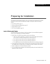
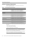
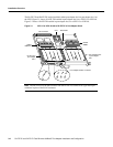
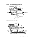
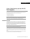
Figure 3-2 VIP2-15 or VIP2-40 with a PA-FE-FX in Port Adapter Slot 0
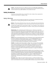
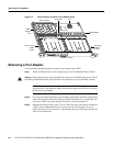
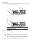
Figure 3-3 shows a PA-FE-TX installed in port adapter slot 0 on a VIP2-50. Figure 3-4 shows a
PA-FE-FX installed in port adapter slot 0 on a VIP2-50.
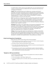
Figure 3-3 VIP2-50 with an PA-FE-TX in Port Adapter Slot 0
H6453
0
FAST ETHERNET
FIBER
LINK
MII
MII
LINK
FIBER
Bus connector
DRAM
SIMMs
SRAM
DIMM U5
PA-FE-FX in
portadapter
slot 0
CPU
U6
U2
U4
Port adapter
handles not shown
Port adapter blank
in port adapter slot 1
Boot ROM
Blank port
adapter
in slot 1
H10470
PA-FE-TX port
adapter
in slot 0
CPU
Bus connector
SRAM
daughter
card
DRAM DIMM
Boot ROM
0
FAST ETHERNET
Handles not shown