


Receptacles, Cables, and Pinouts
PA-FE-TX and PA-FE-FX Fast Ethernet 100BaseT Port Adapter Installation and Configuration
1-8
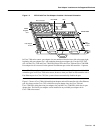
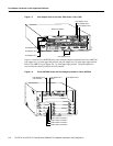
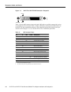
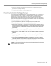
Figure 1-13 PA-FE-TX or PA-FE-FX MII Connection—Receptacle
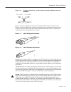
Table 1-2 lists the MII connector pinout and signals. MII cables are available commercially and are
not available from Cisco Systems. Table 1-2 refers to MII cables used between the MII connector on
the PA-FE-TX and an appropriate transceiver. The connection between this transceiver and your
network can be Category 3, 4, or 5, 150-ohm UTP or FTP, or multimode optical fiber.
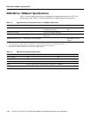
Table 1-2 MII Connector Pinout
Pin
1
1 Any pins not indicated are not used.
In Out In/Out Description
14–17 – Yes – Transmit Data (TxD)
12 Yes – – Transmit Clock (Tx_CLK)
2
2 Tx_CLK and Rx_CLK are generated by the external transceiver.
11 – Yes – Transmit Error (Tx_ER)
13 – Yes – Transmit Enable (Tx_EN)
3 – Yes – MII Data Clock (MDC)
4–7 Yes – – Receive Data (RxD)
9 Yes – – Receive Clock (Rx_CLK)
10 Yes – – Receive Error (Rx_ER)
8 Yes – – Receive Data Valid (Rx_DV)
18 Yes – – Collision (COL)
19 Yes – – Carrier Sense (CRS)
2 – – Yes MII Data Input/Output (MDIO)
22–39 – – – Common (ground)
1, 20, 21, 40 – – – +5.0 volts (V)
Jackscrew Pin 1
Pin 21
H2943