


1-6
PA-POS-1OC3 Single-Port Port Adapter Installation and Configuration Guide
OL-6514-04
Chapter 1 PA-POS-1OC3 Overview
Using Statistics to Estimate Link Loss and Power Budget
Encapsulation Method Support
The following encapsulation methods are supported by the PA-POS-1OC3:
• RFC 1619 PPP over SONET/SDH
We recommend that you refer to the Internet Draft Enabling Transparency for the PPP over
SONET/SDH Mapping, which is recognized by the Internet Engineering Task Force (IETF) and
Internet Engineering Steering Group (IESG) as an approved addendum to RFC 1619.
• High-Level Data Link Control (HDLC)
• Frame Relay
Using Statistics to Estimate Link Loss and Power Budget
Statistical models more accurately determine the power budget than standard worst-case methods.
Determining the link loss with statistical methods requires accurate knowledge of variations in the data
link components. Statistical power budget analysis is beyond the scope of this document. For further
information, refer to ITU-T standards and your equipment specifications.
The following publications contain information on determining attenuation and power budget:
• T1E1.2/92-020R2 ANSI, the Draft American National Standard for Telecommunications entitled
Broadband ISDN Customer Installation Interfaces: Physical Layer Specification.
• Power Margin Analysis, AT&T Technical Note, TN89-004LWP, May 1989.
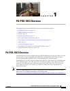
LEDs
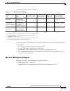
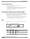
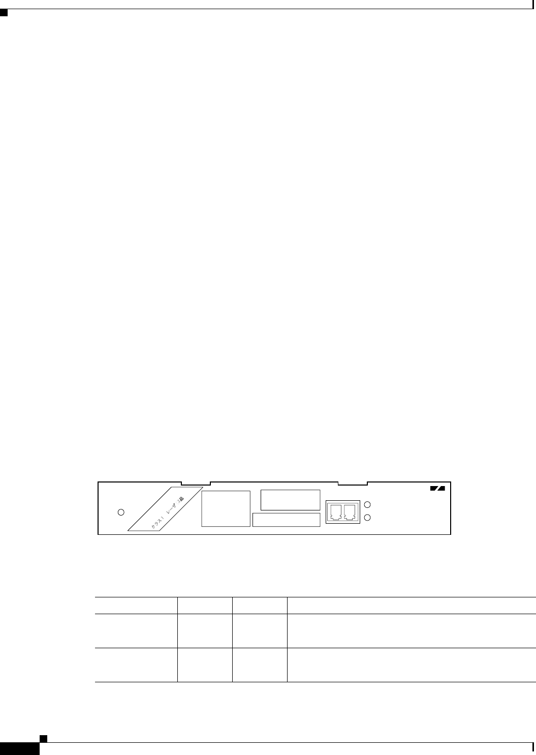
The PA-POS-1OC3 faceplate has three LEDs that indicate port adapter and interface status. (See
Figure 1-2.)
Figure 1-2 PA-POS-1OC-3 LEDs—Faceplate View Shown
Table 1-2 lists the LEDs colors, status, and function.
121578
PA-POS-1OC3
ALARM
ENABLED
RCV
TXRX
POS 0
CLASS 1 LASER PRODUCT
LASERPRODUKT DER KLASSE
1
PRODUIT LASER DE CLASSE 1
PRODUCTO LASER CLASE 1
Table 1-2 PA-POS-1OC3 LEDs
LED Label Color State Function
ENABLED Green On
Off
Enabled for operation
Not enabled
ALARM Orange On
Off
There are SONET alarms on the interface
No alarms