


3-15
PA-POS-1OC3 Single-Port Port Adapter Installation and Configuration Guide
OL-6514-04
Chapter 3 Removing and Installing the PA-POS-1OC3
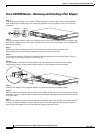
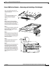
Replacing the SFP Optics Module
To remove the SFP optics module, perform the following steps:
Step 1 Attach an ESD wrist strap to your wrist and to the ESD connection socket on the chassis or to a bare
metal surface on the chassis or frame.
Step 2 Disconnect the network fiber cable from the SFP optics module connector.
Step 3 Remove the SFP optics module from the slot.
a. Using your thumb and forefinger, grip the colored latching band on the front of the SFP optics
module.
b. Gently push the latching band back toward the SFP slot. You may hear a click or feel the SFP optics
module disengage from the holding latch.
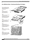
Note Not all SFP optics modules have the same kind of latching mechanism.
c. While still holding the latching band, pull the SFP optics module forward and out of the slot.
Step 4 Set the SFP optics module aside on an antistatic surface.
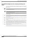
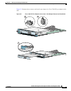
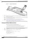
Installing the SFP Optics Module
Use the following procedure to install the SFP optics modules:
Step 1 Attach an ESD-preventive wrist strap between you and an unpainted chassis surface.
Step 2 Verify that you have the correct SFP optics module for your installation.
a. Check the part number and distance information on the SFP optics module label.
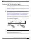
b. If the distance information is not on the label, use the show controller pos x/y command to display
the information after the SFP optics module is installed. See “Verifying the SFP Optics Module
Installation” section on page 3-16 for directions.
Step 3 Align the SFP optics module with the slot so that the label is facing away from the handle.