


— 26 —
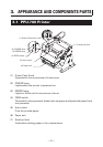
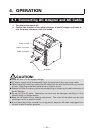
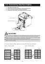
4.2 Connecting Interface Cables
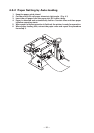
1. Turn the printer power off.
2. Connect the interface connector in the correct direction.
3. Fix the interface connector using a screwdriver.
4. Connect the other end of the interface cable to the host.
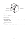
Interface connector
CAUTION!
● Confirm the pin arrangement for the interface connector and cable. Wrong wiring
may result in fault, malfunction, or the like of the computer as well as the printer.
● Always hold the connector when connecting or disconnecting the interface cable.
Holding the cable may cause disconnection of the cable core.
● Confirm that the interface cable is connected securely. Poor contact may result in a
failure in communication.
Power switch
Interface cable
Printer
Pin Signal
2TXD
3RXD
4RTS
6 DSR
7SG
20 DTR
PC
Signal Pin
FG 1
TXD 2
RXD 3
CTS 5
DSR 6
SG 7
DTR 20
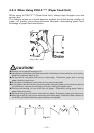
For serial interface cable, use the one with the following connection.
25-pin - 25-pin cable 9-pin - 25-pin cable
Printer
Pin Signal
1FG
2 TXD
3 RXD
4RTS
6 DSR
7SG
20 DTR
PC
Signal Pin
RXD 2
TXD 3
DTR 4
SG 5
DSR 6
CTS 8