


— 28 —
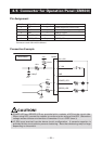
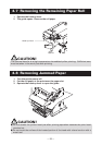
4.5
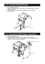
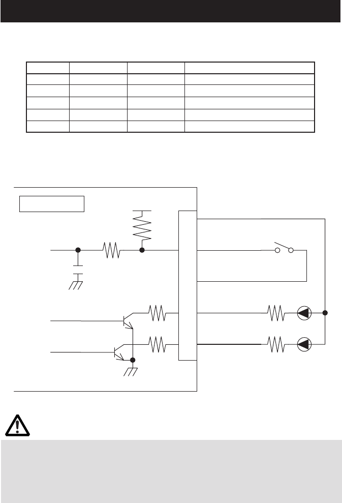
Connector for Operation Panel (CN500)
Pin Assignment
Connection Example
Pin No. Signal Name Input/Output Function
1 Vcc — Power supply for circuit (+5V)
2 LF_SW Input LF switch input (paper feeding)
3 GND — GND for circuit
4 POWER_LED Output POWER_LED output
5 ERROR_LED Output ERROR_LED output
Connector used: 53014-0510 (Molex)
CAUTION!
● POWER LED and ERROR LED are provided with a resister of 47Ω at the circuit side.
When using LED, connect the resister to conform to the rating of the LED. (Saturation
voltage across collector and emitter of transistor VCE(sat)= 0.25V (max.))
● LF_SW input terminal has the above circuit configuration. A ceramic capacitor is
provided at the circuit side to prevent chattering. Note that chattering may be large
depending on the switch.
47Ω
47Ω
1 KΩ
3.3 KΩ
Vcc
1000µF
LF_SW
GND
1
2
3
4
5
CN500
Vcc (+5V)
POWER_LED
ERROR_LED
Control Board