


CBM-710/720 Service Manual
9
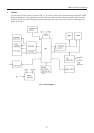
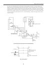
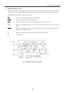
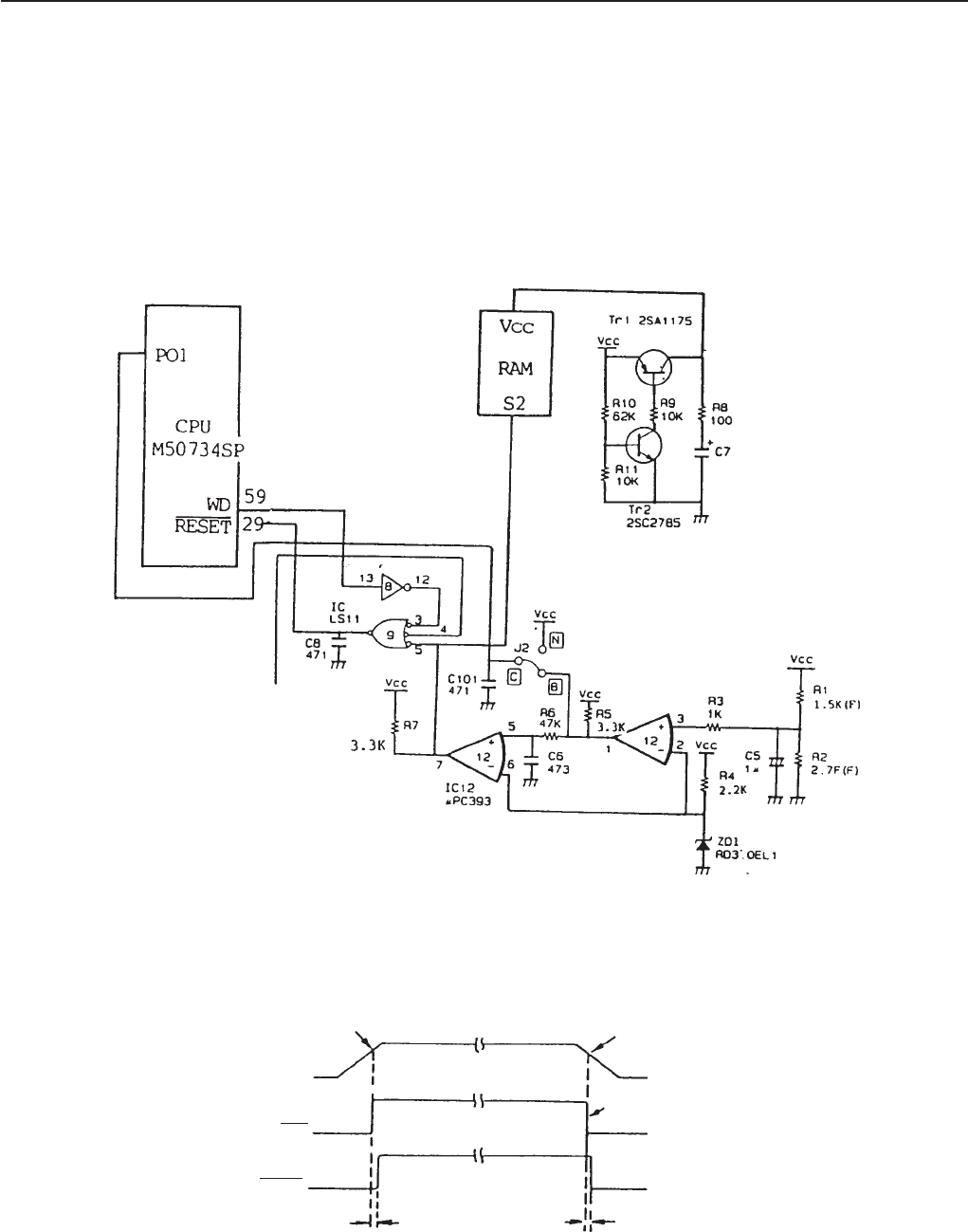
As can be seen in the timing chart, it detects that Vcc decreased up to about 4.5 V for power failure and
generates the power failure interrupt signal and sends it to CPU. Upon receipt of the signal, CPU transmits
the data in its buffer to RAM. This processing is done within about 200 µs. After about 1 ms, the reset signal
is generated at IC12 and given to CPU, etc., causing all circuits to reset for prevention of explosive running.
When the power supply is turned on, reset is released after Vcc increases up to 4.5 V or more and then initial
setting is performed. The WD terminal of CPU is called “Watch Dog”, which is the output terminal used for
explosive running.
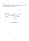
Super Capacitor 0.047F
External Reset Input
(To interface circuit)
Fig. 2-2 Power Failure Interrupt Circuit and Initial Resetting
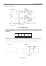
Fig. 2-3 Timing Chart
4.5V
4.5V
Vcc (5V)
INT
(Power Failure Interrupt)
Reset
About 1ms
Power failure interrupt
signal generated
About 1ms (Data stored)