


CBM-710/720 Service Manual
11
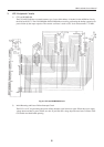
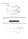
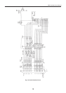
4. Cutter Control Circuit
Cutter Side
Fig. 4-1 Cutter Control Circuit
The cutter control circuit is as shown in Fig. 4-1. In the cutter side, M indicates the motor and S the home switch.
The motor can make forward and reverse rotation by controlling X and Y inputs of the control circuit as shown in
the table below.
Normal
Reverse Stop Stop
HLLHX
LHLHY
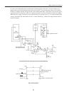
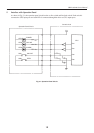
The timing chart is provided in Fig. 4-2. The rising of S when the motor makes forward rotation is the home
position, where the motor stops. For full cut, the blade returns to the home position with only forward rotation of
the motor after turn-around. For partial cut, on the way of cut after forward rotation of the motor, make reverse
rotation to return the blade. Then stop the blade at the home position by making forward rotation again.
1) Full Cut 2) Partial Cut
1 mS 1 mS
15 mS
Fig. 4-2 Timing Chart
X
Y
S
X
Y
S
X
Y
S