


CBM-710/720 Service Manual
12
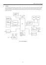
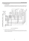
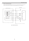
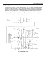
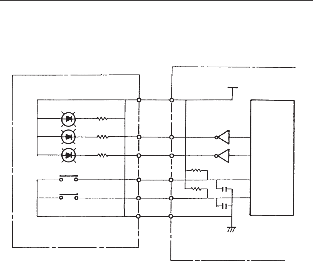
5. Interface with Operation Panel
As shown in Fig. 5-1, the operation panel circuit has the on-line switch and line feed switch. Each switch is
connected to CPU input ports and each LED is connected through the driver to CPU output ports.
Operation Panel Circuit
Control circuit
LED1
LED2
LED3
SW1
SW2
POWER
ON-LINE
ALARM
ON-LINE
FEED
R1
R2
R3
Vcc
CPU
P04
P05
P35
P36
Fig. 5-1 Operation Panel Circuit