


i
CONTENTS
Chapter 1. Printer Disassembly and Assembly ....................................................................................... 1
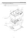
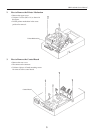
1 How to Remove Upper Cover and Rear Cover ............................................................................................ 2
2 How to Remove The Printer Mechanism...................................................................................................... 3
3 How to Remove the Control Board .............................................................................................................. 3
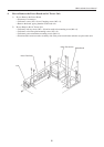
4 How to Remove the Power Board and AC power Unit ................................................................................4
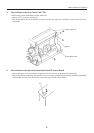
5 How to Remove the Auto Cutter (CBM-720 only)....................................................................................... 5
6 How to Remove the Operation Panel and PE Sensor ................................................................................... 5
Chapter 2. Circuit Description ................................................................................................................. 6
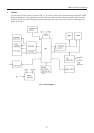
1 Outline .......................................................................................................................................................... 7
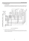
2 CPU Peripheral Circuit ................................................................................................................................. 8
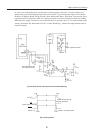
3 Printer Control Circuit ................................................................................................................................ 10
4 Cutter Control Circuit ..................................................................................................................................11
5 Interface and Operation Panel..................................................................................................................... 12
6 Paper End Sensor Circuit ............................................................................................................................ 13
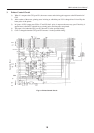
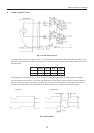
7 Parallel Interface Circuit ............................................................................................................................. 14
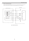
8 Serial Interface Circuit ................................................................................................................................ 16
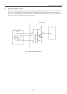
9 RS422A interface Circuit ............................................................................................................................ 18
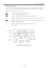
10 Power Supply Circuit .................................................................................................................................. 19
Chapter 3. Auto Cutter ........................................................................................................................... 20
1 Maintenance and Handling ......................................................................................................................... 21
2 Mechanism and Principle of Operation ...................................................................................................... 22
3 Repairing and Troubleshooting................................................................................................................... 24
4 Disassembly and Assembly ........................................................................................................................ 26
Chapter 4. Circuit Diagram .................................................................................................................... 28
1 Power Supply Circuit .................................................................................................................................. 29
2 Noise Filter Circuit ..................................................................................................................................... 30
3 Operation Panel Circuit .............................................................................................................................. 30
4 Paper End Sensor Circuit ............................................................................................................................ 30
5 OP Junction Circuit ..................................................................................................................................... 31
6 Parallel ........................................................................................................................................................ 32
7 RS232C ....................................................................................................................................................... 33
8 PS422A ....................................................................................................................................................... 34
Chapter 5. Parts List ............................................................................................................................... 35
1 Exploded View ............................................................................................................................................ 36
2 Block Diagram ............................................................................................................................................ 41
3 Power Supply Unit ...................................................................................................................................... 43
4 Noise Filter Unit ......................................................................................................................................... 45
5 Control Board Unit: RS232C...................................................................................................................... 47
6 Control Board Unit: Parallel ....................................................................................................................... 51
7 Control Board Unit: RS422A ..................................................................................................................... 55
8 OP Panel/PE Detector/OP Junction Unit .................................................................................................... 59
9 Auto Cutter ................................................................................................................................................. 63
10 Winder......................................................................................................................................................... 67