


CBM-710/720 Service Manual
14
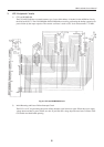
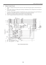
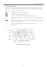
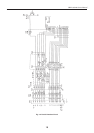
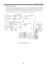
7. Parallel Interface Circuit
This circuit conforms to the standard interface. Description will be made for each signal of interface connector as
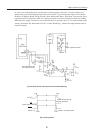
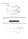
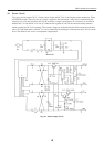
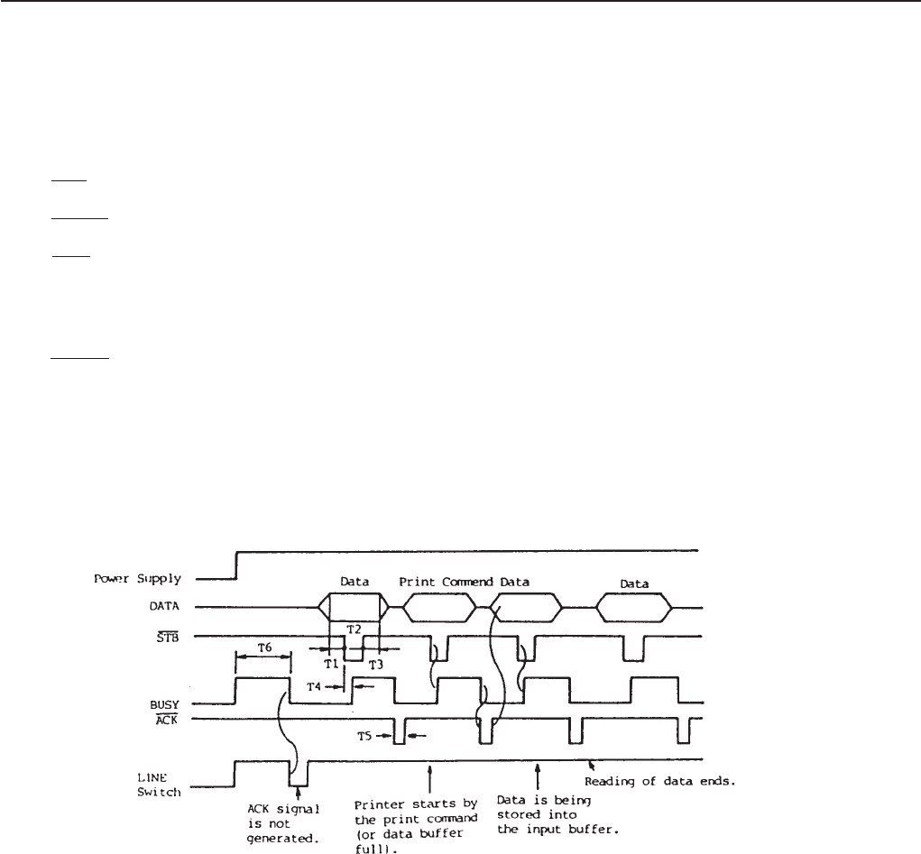
follows. Fig. 7-1 shows the data input and print timing chart and Fig. 7-2 the parallel interface circuit diagram.
DATA (D1~D8) : 8-bit parallel signal (Positive logic)
STB : Strobe signal for reading 8-bit data (Negative logic)
RESET : Signal for resetting the printer (Negative logic)
ACK : Data request signal to be output at the end of BUSY signal (Negative logic)
BUSY : Signal for indicating if the printer is in the busy state; it goes into the busy state for H. (Positive
logic)
FAULT : Signal to be output when the printer is in the abnormal state; at this time all control circuits in
the printer stop. (Negative logic)
PE : Signal to be output when the print paper becomes short (Positive logic)
FG : Frame ground
Fig. 7-1 Data Input and Print Timing Chart