


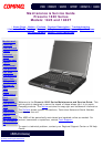
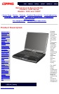

Maintenance & Service Guide
Presario 1800 Series
Models: 1825 and 1800T
| Home Page | Notice | Preface | Product Description | Troubleshooting
Illustrated Parts Catalog | Removal & Replacement Procedures | Specifications
Pin Assignments | Battery Pack Operations
Connector Pin Assignments
This section provides connector pin assignment tables for Compaq Presario 1800 Series Portable
Computers. For more information on connectors, refer to the sections on Back Connectors and Port
Replicator Connectors.
NOTE: The signals in all tables of this appendix are considered active high unless otherwise
indicated by an asterisk (*).
Parallel Connector
Pin Signal Pin Signal
1 Strobe* 10 Acknowledge*
2 Data Bit 0 11 Busy
3 Data Bit 1 12 Paper Out
4 Data Bit 2 13 Select
5 Data Bit 3 14 Auto Linefeed*
6 Data Bit 4 15 Error*
7 Data Bit 5 16 Initialize Printer*
8 Data Bit 6 17 Select In*
9 Data Bit 7 18-25 Signal Ground
* = Active low
Top of Page
Serial Connector
Connector Pin Signal
1
2
3
4
5
6
7
8
9
Carrier Detect
Receive Data
Transmit Data
Data Terminal Ready
Signal Ground
Data Set Ready
Ready to Send
Clear to Send
Ring Indicator
Keyboard/Mouse
Connector Pin Signal
1
2
3
4
5
6
Data 1
Data 2
Ground
+5 V
Clock 1
Clock 2
Top of Page
External VGA Monitor
Connector Pin Signal
1
2
3
4
5
6
7
8
9
10
11
12
13
14
15
Red Analog
Green Analog
Blue Analog
Not connected
Ground
Ground Analog
Ground Analog
Ground Analog
+5V
Ground
Monitor Detect
DDC2B Data
Horizontal Sync
Vertical Sync
DDC2B Clock
Top of Page
Universal Serial Bus
Connector Pin Signal
1
2
3
4
+5V
Data -
Data +
Ground
Top of Page
Modem
Connector Pin Signal
1
2
3
4
5
6
Unused
Tip
Ring
Unused
Unused
Unused
Top of Page
TV Out
Connector Pin Signal
1
2
3
Ground
Composite
Ground
Top of Page
Game Port
Connector Pin Signal
1
2
3
4
5
6
7
8
9
10
11
12
13
14
15
+5V
SWA
RBTA
GND
GND
RBTB
SWB
+5V
+5V
SWC
RBTC
RMSO
RBTD
SWD
RMSI
Top of Page
S Video
Connector Pin Signal
1
2
3
4
Ground
Ground
SYR
SCG
Top of Page
Port Replicator Connector
Pin Signal Pin Signal Pin Signal Pin Signal
1 Adapter Power 21 Serial Port CTS 41 Not Connected 61 Switch C
2 Adapter Power 22 Serial Port DCD 42 Power Cycle 62 Switch D
3 Adapter Power 23 Serial Port DSR 43 Keyboard Clock 63 MIDI Input
4 Adapter Power 24 Serial Port TXD 44 Keyboard Data 64 MIDI Output
5 Adapter Power 25 Serial Port RTS 45 Mouse Clock 65 Not Connected
6 Adapter Power 26 Monitor DDC 46 Mouse Data 66 USB Power
7 Not Connected 27 Monitor DDC 47 Lp Select 67 USB Power
8 Printer Data 0 28 Monitor Indicator 48 Lp Paper End 68 USB Power
9 Printer Data 1 29 V. SYNC 49 Lp Initialize 69 USB Power
10 Printer Data 2 30 Ground 50 Lp Busy 70 USB A-
11 Printer Data 3 31 H.SYNC 51 Lp Error 71 USB A+
12 Printer Data 4 32 Ground 52 Lp Acknowledge 72 USB B-
13 Printer Data 5 33 Blue 53 Lp AutoFeed 73 USB B+
14 Printer Data 6 34 Ground 54 Lp Strobe 74 5V
15 Printer Data 7 35 Green 55 Joystick Data A 75 5V
16 Lp Indicator 36 Ground 56 Joystick Data B 76 Not Connected
17 Port Replicator Dock
Indicator
37 Red 57 Joystick Data C 77 S-Video SYR
18 Serial Port RXD 38 Ground 58 Joystick Data D 78 Ground
19 Serial Port RI 39 Composite TV Out 59 Switch A 79 S-Video SCG
20 Serial Port DTR 40 Not Connected 60 Switch B 80 Ground
Top of Page
privacy and legal statement