


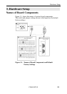
Hardware Setup
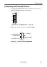
COM-2(PC)F26
Interrupt Level Setting
The signal from the LSI (NS16550 equivalent) on the board can be
used as an interrupt request signal based on the JP1, JP2, and JP3
settings.
Note!
When using interrupts, set an interrupt level that is not used by any
other device.
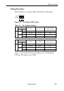
Setting Procedure
When not Using Interrupts
Place a short connector on the NC pin of each jumper (JP1, JP2, and
JP3).
When Using Interrupts
Connect the interrupt level using the short connector on each
jumper (JP1, JP2, and JP3). Available interrupt levels are IRQ3 to
7, 9 to 12, 14, and 15.
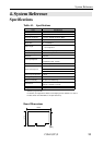
JP1
Enhanced
JP2
COM CN1
JP3
COM CN2
9
3 4 5
6
7 10 11
1214
15
NC
9
3 4 5 6 710 111214
15
NC
9
3 4 5
6
7 10 111214
15
NC
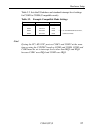
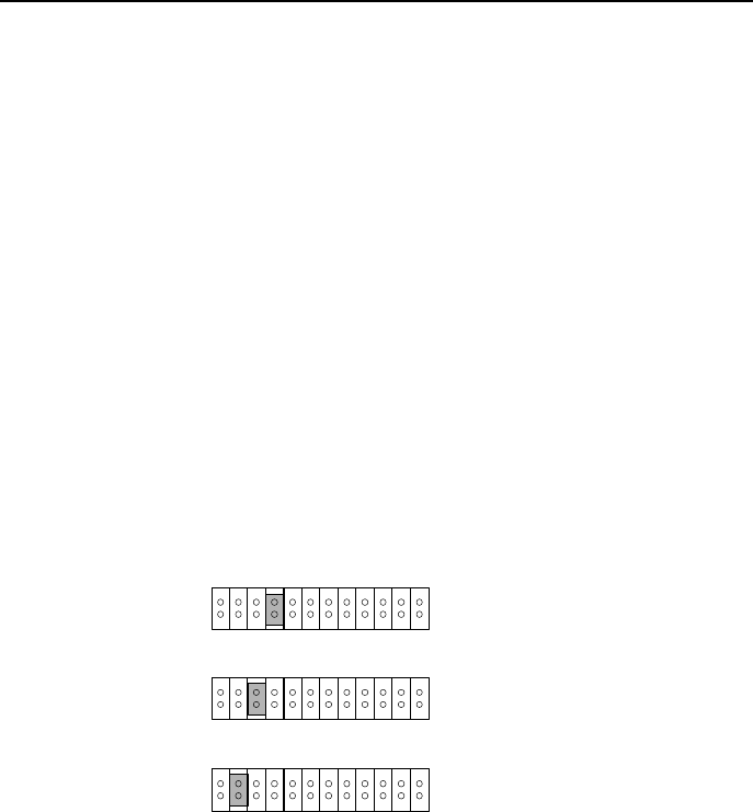
Figure 3.3. Interrupt Level Settings
If SW1 selects Enhanced mode, the settings in Figure 3.3. specify
that CN1 and CN2 both use IRQ5. If Compatible mode is set, the
settings specify that CN1 uses IRQ4 and CN2 uses IRQ3.
Note!
Jumper of the mode which isn’t used is to connect a short connector
to the NC pin.