


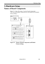
Hardware Setup
COM-2(PC)F 31
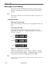
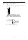
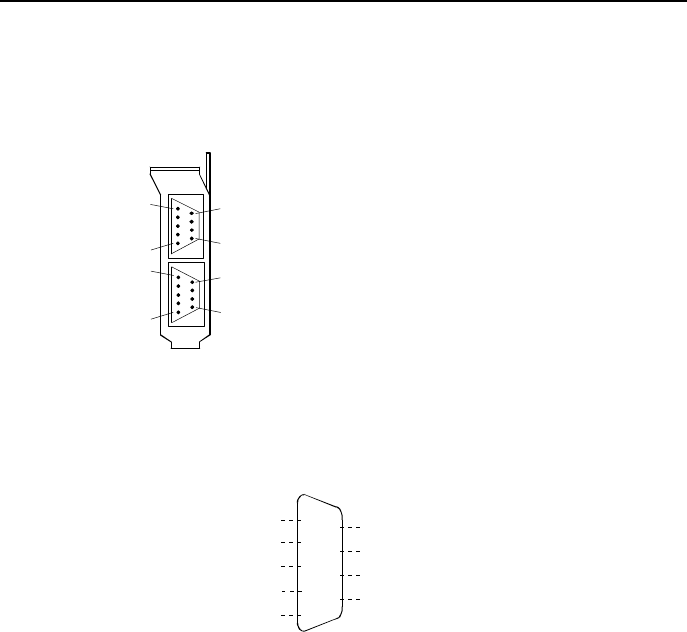
Connecting the External Devices
Connecting the COM-2(PC)F board to external devices is via two
9-pin D-SUB connector (male) on the board.
CN1
CN2
5
9
1
6
5
1
9
6
On-board Connector : DELC-J9PAF-20L9 (Male) [mfd. by JAE]
Application Connector : 17JE-13090-02 (D8C) (Female) [mfd. by DDK]
Figure 3.8. Interface Connectors (CN1 and CN2)
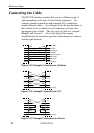
(Data Terminal Ready) DTR
RI (Ring Indicator)
CTS (Clear to Send)
RTS (Request to Send)
DSR (Data Set Ready)
5
4
3
2
1
9
8
7
6
(Transmit Data) TXD
(Receive Data) RXD
(Signal Ground) SG
CN1/CN2
(Data Carrier Detect) DCD
Figure 3.9. CN1 and CN2 Pin Assignments