


Installing the AlphaServer IP Platform Hardware
2–6
AlphaServer Intelligent Peripheral Platform Hardware Owner's Guide
2.4.1.1.2
Connecting Dialogic DTI/212 E-1 Modules (75-Ohm)
The Dialogic DTI/212 E-1 modules come in 75-ohm and 120-ohm versions. If you have a
DTI/212 120-ohm module, see Section 2.4.1.1.3. Refer to the Dialogic Network Hardware
Reference for additional information on DTI/212 E-1 modules.
On the rear bracket of the DTI/212 75-ohm module are two BNC-type jacks for connecting to
the external E-1 network. The cabling between these jacks and the external E-1 network
should be 75-ohm coaxial. The DTI/212 end of the cable should consist of a BNC-type male
connector. The user is responsible for supplying an appropriate cable for these connections.
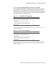
The pin designations for the DTI/212 75-ohm cable ends are given in Table 2-3.
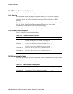
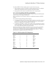
Table 2-3: E-1 to DTI/212 75-Ohm Pin Designations
Signal Jack/Pin
Transmit data: output from DTI/212 (tip) J201A center
Transmit data: output from DTI/212 (ring) J201A shield
Receive data: input to DTI/212 (tip) J201B center
Receive data: input to DTI/212 (ring) J201B shield
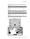
To cable the DTI/212 75-ohm module to the E-1 network, follow these steps:
1.
Attach the appropriate end of the E-1 to DTI/212 (receive) cable to jack J201B on the
rear bracket of the DTI/212 module. Carefully push the BNC connector onto the jack and
lock by turning a quarter-turn clockwise.
2.
Attach the appropriate end of the DTI/212 to E-1 (transmit) cable to jack J201A on the
rear bracket of the DTI/212 module. Carefully push the BNC connector onto the jack and
lock by turning a quarter-turn clockwise.
2.4.1.1.3
Connecting Dialogic DTI/212 E-1 Modules (120-Ohm)
On the rear bracket of the DTI/212 120-ohm module is an RJ-48C jack for connecting to the
external E-1 network. The cabling between this jack and the CSU should be 120-ohm twisted
pair or equivalent. The DTI/212 120-ohm end of the cable should consist of an RJ-48C plug.
The user is responsible for supplying an appropriate cable for these connections. The pin
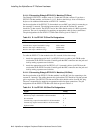
designations for the DTI/212 120-ohm cable ends are given in Table 2-4.
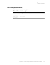
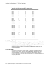
Table 2-4: E-1 to DTI/212 120-Ohm Pin Designations
Signal Pin(s)
Receive ring: input to the DTI/212 120-ohm module 1
Receive tip: input to the DTI/212 120-ohm module 2
No connection 3, 6
Transmit ring: output from the DTI/212 120-ohm module 5
Transmit tip: output from the DTI/212 120-ohm module 4
Optional shield 7, 8